Learn Automation with MINATA #07: Measuring Voltage With a Meter: Five Steps to Avoid a Wrong Reading
Learn Automation with MINATA #07: Measuring Voltage With a Meter — Five Steps to Avoid a Wrong Reading
A digital multimeter only shows the result of the connection the user chose. It does not know that a lead is in the wrong socket, that the range is unsuitable, or that the test point sits in a panel whose energy exceeds what the instrument can survive. Reading the number is therefore not enough. A good measurement answers three questions at once: what quantity is being measured, at which two points, and under what safety conditions.
This article covers how to prepare and read a measurement. It does not replace electrical safety training, a risk assessment, or the procedure in force at your site. Only a competent person may measure on or near parts that can be live.
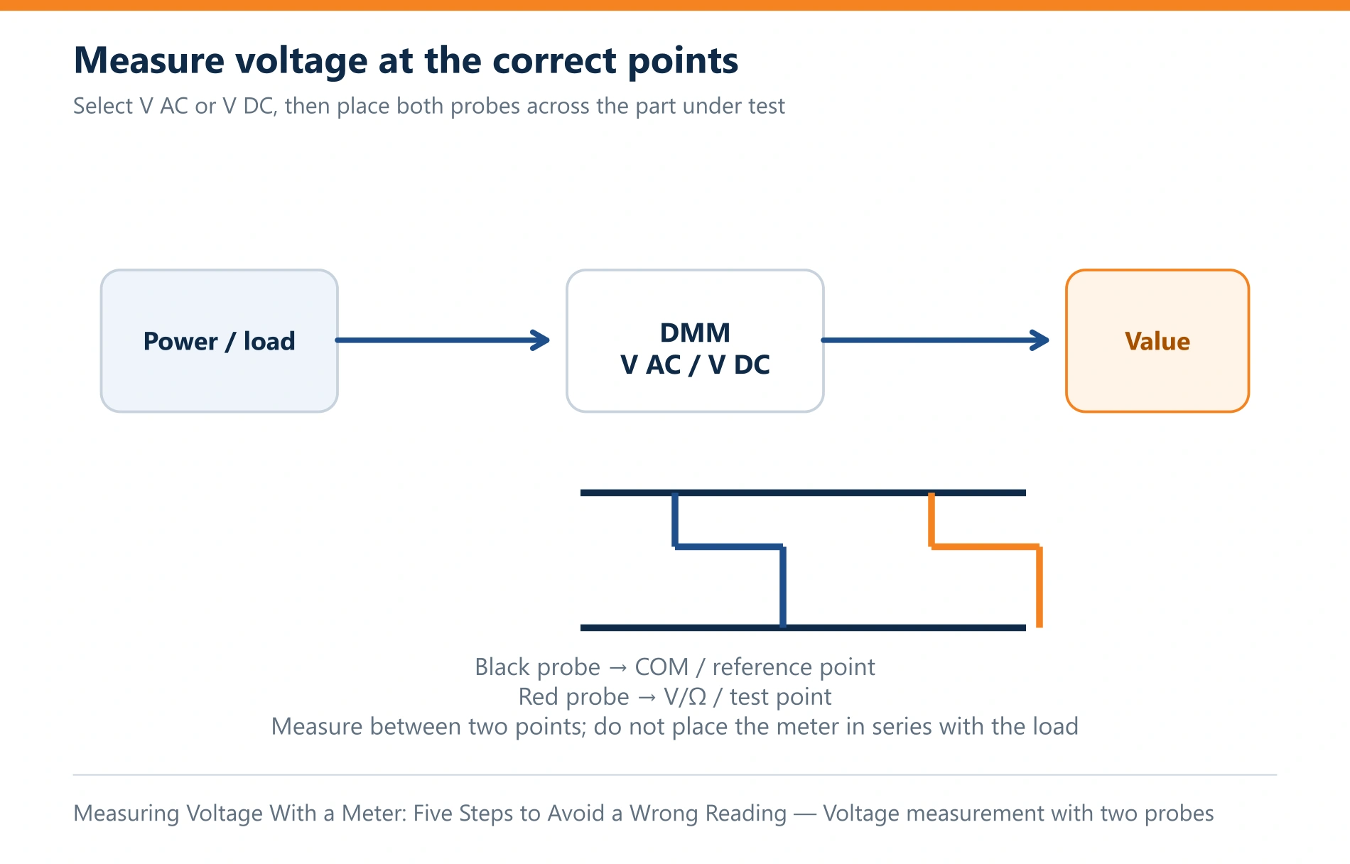
1. Start from the technical question, not from the rotary switch
"The machine is not running" is not yet a measurement question. Turn the symptom into a hypothesis that can be tested:
- Does 24 VDC reach the PLC input?
- Is the protective contact open?
- Does the sensor produce the right signal when a part passes?
- Is the conductor broken, checked with the circuit isolated?
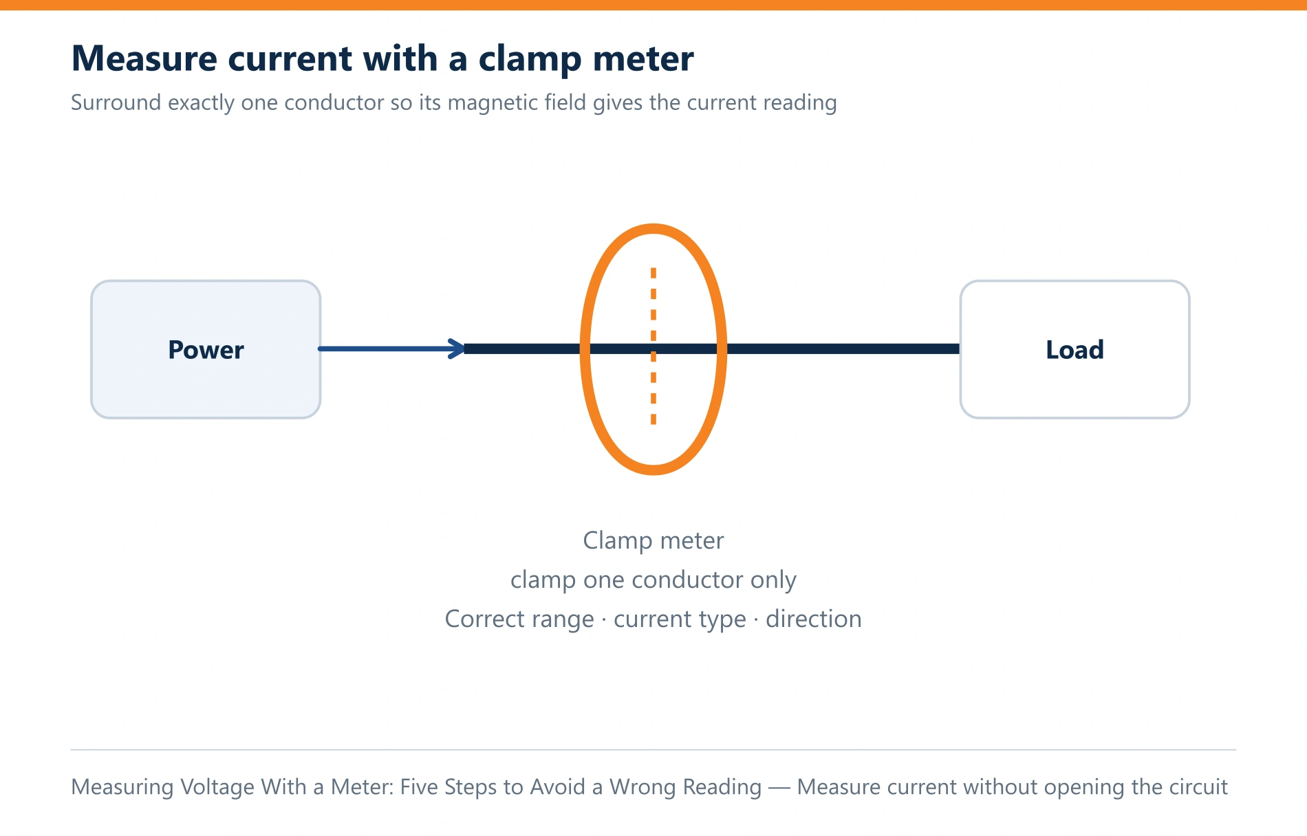
Each question leads to a different quantity and a different connection. Voltage is measured between two points. Current normally requires the instrument to sit in the current path, or a suitable clamp. Resistance and continuity are only checked after the circuit has been isolated and confirmed dead. Do not use the continuity function as a safety detector.
| Question to answer | Suitable quantity | Condition that matters |
|---|
| Does supply reach the load? | AC or DC voltage | Identify the reference point and the expected level |
| Is the conductor continuous? | Resistance / continuity | Isolate the supply, deal with stored energy |
| How much does this branch draw? | Current, or a clamp meter | Right method, right socket, right range, right current type |
| Is the signal switching correctly? | Frequency or voltage; sometimes an oscilloscope | A DMM may average and miss a short pulse |
2. Check the meter, the leads and the measurement category
Before opening a panel, check the meter case, the display, the battery, the input protection fuse and the insulation of the leads. A cracked tip, too much exposed metal, or a conductor broken inside the insulation all make the reading unstable and raise the risk of a short. Fluke advises checking the condition and rating of test leads before use; leads and meter must suit the environment being measured.
Measurement categories CAT I to CAT IV are not simply a maximum voltage. They describe the ability to withstand transient overvoltage at different positions in the installation. A distribution panel, a load branch and an electronics circuit do not share the same transient environment. Use an instrument whose voltage rating and category match the point of measurement or exceed it, and follow the manufacturer's instructions and the rules at your site.
Three checks that are easily skipped:
- Black lead in COM; red lead in the correct V/Ω or A/mA socket.
- Rotary switch on the right quantity, and on the right AC or DC setting.
- A range large enough for the expected value; if the value is unknown, start at the higher range the instrument's instructions recommend.
Leaving a lead in the current socket is a particularly dangerous mistake: if the lead is still in A/mA when the user measures voltage between two points, the path through the fuse is close to a short circuit. After every current measurement, return the leads to the usual voltage configuration, following your site procedure.
3. Prefer isolation; a live measurement needs a reason
OSHA 1910.333 requires live parts that a worker may be exposed to be de-energised before work, unless de-energising introduces a greater hazard or is infeasible because of design or operating limits. Measurement can be one of the tasks that is only possible with the circuit energised — but that does not make it a routine activity for everyone.
Where the measurement must be made live, a competent person applies work practices, protective equipment, insulated tools and approach limits suited to the level of hazard. Keep the exposed time as short as possible: read the diagram, identify the test points in advance, prepare the instrument, and know the plausible range before the panel is opened.
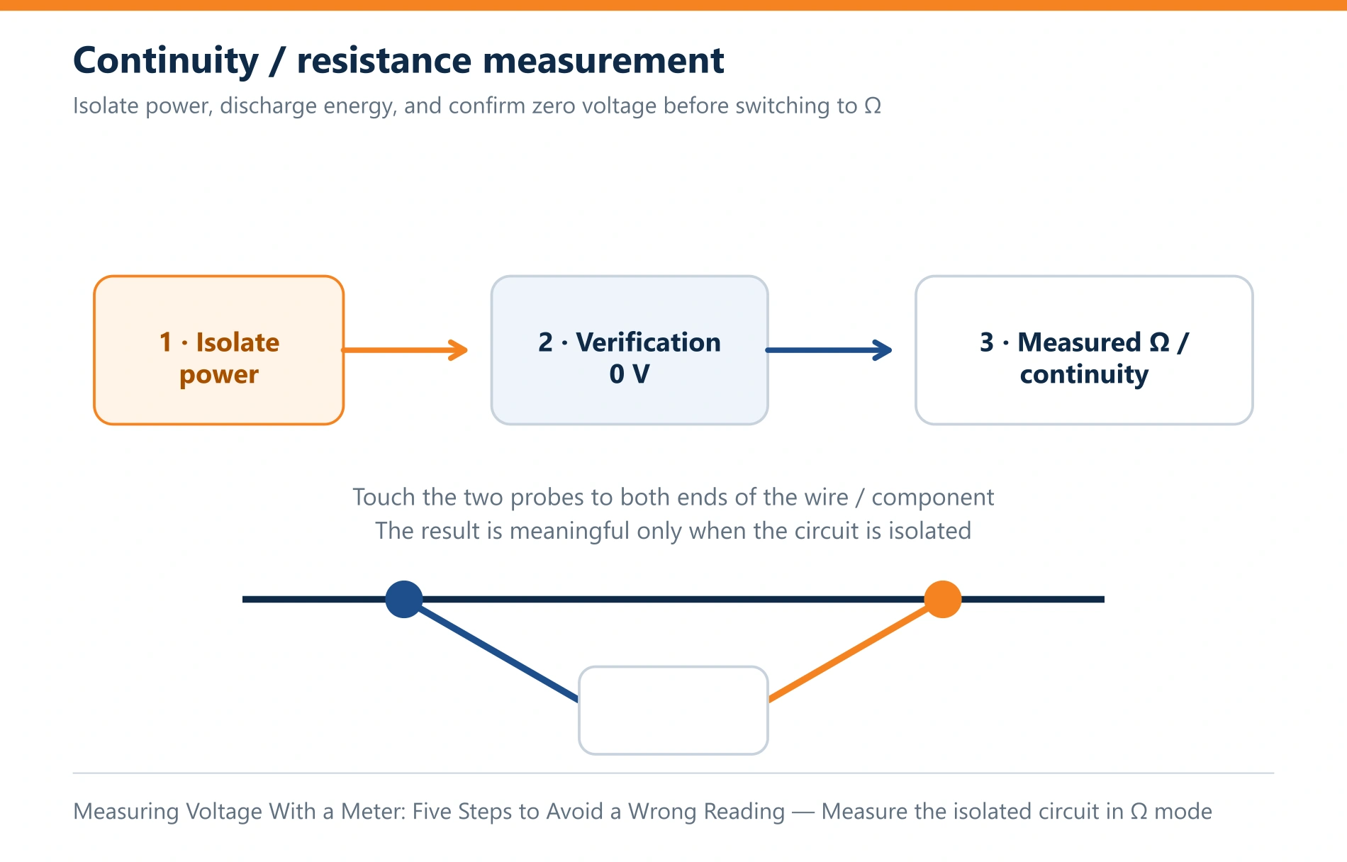
For resistance, diode or continuity measurements, isolate the supply and confirm the dead state first. Capacitors, DC-link supplies, regenerative drives or a back-feed from another circuit can all hold voltage after the main switch has been turned off.
4. Prove the instrument works: live – dead – live
When the aim is to confirm the absence of voltage, a reading of "0 V" may mean the circuit is safe — or that a lead is broken, that a fuse or the instrument has failed, or that the socket or mode is wrong. The live – dead – live method removes that blind spot:
- Check the instrument on a known live source of a suitable level.
- Measure at the points to be confirmed on the isolated equipment.
- Check the instrument again on the known source.
Fluke describes live-dead-live as an essential part of proving the absence of voltage. OSHA likewise requires a qualified person to use test equipment to verify that the parts to be contacted have been de-energised; for circuits above 600 V nominal, OSHA states that the test instrument shall be checked immediately before and immediately after that verification.
While measuring, keep fingers behind the barrier on the probe, avoid letting a tip slip between two terminals, and never change sockets while the leads are connected to a circuit. Record the condition as well as the number: "23.8 VDC between +24V and 0V while the valve is commanded ON" is worth more for diagnosis than "23.8 V".
5. Read the result against the circuit, not against a feeling
A plausible number can still lead to a wrong conclusion when the reference point is wrong. A PLC output may show close to 24 V with no load and collapse once the valve coil is connected; an induced voltage can appear on a disconnected conductor; a fast pulse can be averaged away by the DMM.
Compare the result against three layers of evidence:
- the wiring diagram and the equipment labels;
- the command and feedback state at the moment of the measurement;
- a reference measurement nearer the source, or on an equivalent channel known to work.
Case: a 24 VDC valve that does not actuate
The PLC reports the output ON, but the valve does not move. A logical sequence of checks:
- Confirm the mechanical and pneumatic conditions and the safety procedure first.
- From the diagram, identify the two coil terminals and the expected value.
- Measure the voltage across the load, while commanded, rather than one conductor against the enclosure.
- If the voltage is correct and the valve still does not move, check the coil and the connector with the circuit isolated.
- If the voltage is missing, trace back through the terminal block, the protective contact and the output, following the diagram.
This separates a control fault, a wiring fault and an actuator fault by evidence, instead of replacing parts on a guess.
Checklist before leaving a measurement
- The leads are back in the correct socket and the safe mode, per procedure.
- The instrument has been re-checked if the measurement was used to prove a dead state.
- Covers, barriers and guards are refitted and the equipment is returned to a permitted state.
- The measured value and the condition under which it was taken are recorded.
Public references
- OSHA 29 CFR 1910.333 — Selection and use of work practices.
- Fluke — guidance on test lead condition and on proving the absence of voltage (live-dead-live).
View all MINATA technical articles