Learn Automation with MINATA #09: Pushbuttons, Selector Switches and Pilot Lights — The Simple Interface of an Automated Machine
Pushbuttons, selector switches and pilot lights: the simple interface of an automated machine
A packaging machine stops mid-shift. The operator looks up at the panel: the green light is still on, but the conveyor is not running. He presses Start a few more times, nothing happens, and calls maintenance. It turns out the green light was wired straight from the "run enable" command rather than from the motor's real feedback — the light stayed on while the thermal overload had already tripped. Fifteen minutes of downtime because of a light that "lied".
On an automated machine, the operator rarely touches the PLC or reads the program. What they touch every day are the pushbuttons, selector switches and pilot lights on the panel face. This is the simplest part of the interface, yet it decides whether the operator understands where the machine is, what it is allowed to do, and what to check next.
Choosing the wrong colour, assigning a vague function, or keeping inconsistent indicators is not a cosmetic issue. It leads to wrong actions, slow reaction in an incident, and shift-to-shift arguments about "what does this light mean". A simple interface does not mean a careless one — it means making each signal carry exactly one clear meaning.
This article explains design principles. Colour codes and safety requirements must follow the standards applicable at the operating site (for example IEC 60204-1 for the electrical equipment of machines, IEC 60073 for indicator colour codes, ISO 13850 for emergency stop) and each machine's or customer's own rules.

A simple interface must not be done carelessly
The operator decides in seconds based on what they see and press. If "Start" is red on this machine but "Stop" is red on the one next to it, sooner or later someone presses the wrong one. If a yellow light sometimes means "running" and sometimes "warning", the operator learns to ignore it — and misses it when it truly matters.
The root principle is simple: one colour, one meaning, kept consistent across the whole machine and across machines in the shop. Colour standards exist to do exactly this, not to decorate.

Pushbuttons: momentary and maintained
Before discussing colour, understand how a button holds its state:
- Momentary button: acts only while pressed; release it and it returns. This is the most common type for Start, Stop, Reset, Jog. Because the signal exists only while pressed, the PLC must latch that state with a hold circuit (covered in the latching-circuit article).
- Maintained button: press once to latch, press again to release. Used for commands that should keep their physical state even after control power is lost.
- Illuminated pushbutton: combines button and pilot light, handy in tight space, but it must be clear whether the light indicates command received or the real state of the mechanism — the two differ.
Pushbutton colour is not decoration
Under IEC 60204-1, the actuator colour of a pushbutton follows its function:
| Colour | Meaning | Example use |
|---|
| Red | Stop / Off; act in an emergency | Stop, Off, emergency stop (E-stop, see below) |
| Green | Start / Run / On | Start, On |
| Yellow / Amber | Intervene to suppress an abnormal condition; restart an interrupted cycle | Fault reset, intervention |
| Blue | A function requiring a mandatory action | Mandatory reset, confirm command |
| White / Grey / Black | No specific assigned meaning; general commands | Jog, commands not in the groups above |
The two most important rules to remember:
- START prefers green and must never be red.
- STOP prefers red; never use green for stop.
For a button that alternates Start and Stop (push-on/push-off), use white, grey or black — not red, not green — to avoid misreading.
The emergency stop (E-stop) is not an ordinary pushbutton
Many people treat the E-stop as a "bigger Stop button". It is not. The emergency stop is a safety device under ISO 13850 and IEC 60204-1, with mandatory features:
- A red mushroom head on a yellow background, easy to see and reach.
- Latching: pressing holds the stop state; it must be deliberately twisted/pulled to release — it does not spring back on its own.
- Uses a normally-closed contact with direct (positive) opening — when pressed, the contact is mechanically forced open, independent of any spring, so it still breaks even if the contact has welded.
- Releasing the E-stop only clears the latch; it must not let the machine move again on its own (detailed in the machine-safety article).
- Do not use the E-stop as a normal operational stop. A normal in-cycle stop must have its own Stop button.
In other words: red-on-yellow and a latching mechanism signal "this is human safety" — do not mix it with process control buttons.
Selector switches: choosing a mode and holding it
A selector switch sets the operating mode, not an instantaneous command:
- 2 or 3 positions, with key-operated versions to restrict who can change mode.
- It is a maintained device: the position stays until the operator turns it, so the PLC reads it as a permanent condition (for example, in Manual or Auto).
- Typical example: Off / Manual / Auto. Manual allows jogging each mechanism; Auto allows the cycle to run.
Common pitfall: switching mode mid-run. Turning from Auto to Manual while the machine is running must be handled safely (stop motion, hold the load, no step jump), not merely flip a bit in the PLC. Manual and Auto must share one set of safety conditions.
Pilot lights: one colour, one message
Indicator light colours under IEC 60204-1 / IEC 60073 map to machine state and operator action:
| Colour | State | What the operator should do |
|---|
| Red | Fault / danger, act now | Intervene immediately |
| Yellow | Abnormal / warning, approaching a limit | Monitor or prepare to intervene |
| Green | Normal / ready / safe | No action needed |
| Blue | Mandatory: a specific action is required | Perform the requested action |
| White | General information / neutral | Monitor |
A few practical notes:
- Flashing versus steady: a flashing light usually draws attention or distinguishes "pending / about to happen" from "established". Flash conventions must also be consistent.
- Lamp test: provide a way to test for a burnt-out bulb — a "safe" green light that has failed silently hides information.
- Do not let a light lie: a light should reflect the real state taken from feedback, not merely the command sent. (Exactly the story at the start.)

Installation and wiring: what decides durability
The mechanical-electrical side of buttons and lights decides how long the machine runs reliably:
- Standard cut-out size: most common is Ø22 mm (with Ø16 mm and Ø30 mm for special uses). Pick one size and keep it consistent across the panel to share accessories.
- Separate contact blocks: the button/light body usually detaches from the contact block. One button head can stack several NO/NC blocks — so one Start button can feed a PLC input and close an auxiliary circuit at once. NO/NC details are the subject of article #10.
- Protection rating (IP): panel faces in damp, dusty shops should use buttons/lights rated IP65 or higher; jet-water environments need more.
- Pilot light voltage: prefer 24 VDC LED lamps for modern control panels — long life, low current, matched to PLC/relay outputs. Note the voltage on the drawing to avoid fitting a 220 V bulb by mistake.
- Contact current: button contacts carry small currents. Do not use a button contact to switch a large load directly (motors, high-power valves) — let the button drive a relay/contactor, and let that device switch the load (articles #11, #12).
- Neat, numbered wiring: every wire from a button/light back to the terminal strip must be numbered, matching the I/O list. Keep signal wires away from power wires to avoid noise.
From the panel face to PLC logic
Buttons and lights are only the start and end points; logic sits in between. The diagram below summarises the full path of a typical Start signal:
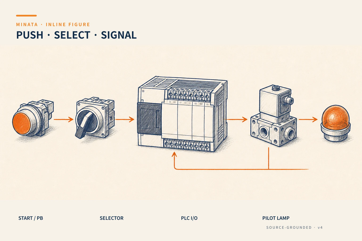
- A momentary Start/Stop button needs a latching circuit in the PLC to hold the state after release.
- The E-stop breaks the latch directly — even if the operator is holding Start, the run state must fall to 0.
- Whether a button uses a normally-open or normally-closed contact (NO/NC) decides how the machine behaves on a broken wire or lost signal — exactly the topic of the next article, #10.
- The pilot light should be driven from real state feedback, not from the output just energised (an energised coil does not mean the mechanism has actually moved).
A MINATA engineering reference
The illustration below is a reference approach following MINATA design thinking; final parameters and configuration must be confirmed against the actual records, standards and devices.
On MINATA machine cells controlled by Delta AX-308E (CODESYS), a minimal panel face typically has: a green Start button, a red Stop button, an Off/Manual/Auto selector, one E-stop (red mushroom on yellow) and three lights — green (running) / yellow (warning) / red (fault).
How the logic connects:
- Start (momentary) goes to a digital input; in ST, a
bRun variable is set when Start plus the enabling conditions are present, and reset on Stop or loss of the safety circuit. - The E-stop passes through a hardware safety circuit first; only then does its state report to the PLC for display — the PLC is not the sole protective layer.
- The green light is not driven from
bRun but from real feedback of the mechanism (for example the drive's running signal or a motion sensor), to avoid the "lying light" fault from the opening. - The yellow light groups "not stopping the machine but needs attention" warnings; the red light groups faults that stop the cycle.
By keeping the colour conventions and driving lights from feedback, the next shift's operator understands the machine's state at a glance, without asking the previous shift.
Common mistakes
- Using a red button for Start or a green one for Stop "because it looks nice".
- Treating the E-stop as a bigger Stop button, even using it to stop at end of shift.
- Wiring the "running" light straight from the command instead of real feedback.
- Mixing cut-out sizes (Ø16/Ø22/Ø30) in one panel, leading to a messy accessory stock.
- Using a button contact to switch a large load directly instead of via a relay/contactor.
- Having no lamp test, letting a bulb fail silently and hide safety information.
Checklist for a button–switch–light interface
- [ ] Each button, switch and light has one function and a clear label.
- [ ] Colours follow the standard and are consistent across the machine/shop.
- [ ] Start is not red; Stop is not green.
- [ ] The E-stop is a red-on-yellow mushroom, latching, positive-opening, separate from the ordinary Stop.
- [ ] The mode selector handles a mid-run change safely.
- [ ] Lights reflect real state and have a bulb-test mechanism.
- [ ] Momentary buttons have a matching latching circuit in the PLC.
- [ ] Cut-out size, IP rating and lamp voltage are noted on the drawing.
The button–switch–light interface is what the operator faces every shift. Making it consistent and honest is the first step toward a machine that is both easy to use and safe.
Read more automation knowledge at MINATA: https://minatavn.com/en/blog/industrial-automation
Previous — #08: Energy isolation, lockout and tagout before machine repair: https://minatavn.com/en/blog/automation-08-lockout-tagout-energy-isolation
Next — #10: Normally-open and normally-closed contacts (NO/NC): https://minatavn.com/en/blog/automation-10-no-nc-contacts
View all MINATA technical articles