Learn Automation with MINATA #10: Normally-Open and Normally-Closed Contacts (NO/NC) — The Foundation of Every Safety Circuit
Normally-open and normally-closed contacts (NO/NC): the foundation of every safety circuit
A signal wire from an emergency-stop button is chewed through by a rodent inside the cable tray. Nobody knows. The machine runs fine for a week — until the day something goes wrong, the operator slams the E-stop, and… the machine does not stop. Had that E-stop been wired correctly as normally closed (NC), the broken wire would have stopped the machine on day one, and the fault would have been found immediately instead of at the worst possible moment.
This is why a concept that sounds so "elementary" — normally-open (NO) and normally-closed (NC) contacts — is the foundation of every safe control circuit. Choosing the wrong contact type does not make the machine misbehave today; it leaves a trap that springs at exactly the worst time.
This article explains what NO/NC are, how to read their symbols on a drawing, the fail-safe principle, why Start is usually wired NO while Stop/E-stop must be NC, and how to bring NO/NC signals correctly into a PLC input.
This article presents principles. Specific safety requirements (contact type, integrity level, monitoring) must follow the applicable standards — for example IEC 60204-1 for the electrical equipment of machines, ISO 13849 for safety-related parts of control systems, ISO 13850 for emergency stop — and each machine's risk assessment.

NO and NC: defined by the "rest" state
The word "normally" refers to the contact state when no action is applied — button not pressed, relay not energised, sensor not detecting:
- Normally-open — NO: at rest it is open, no current flows. When actuated, it closes and conducts.
- Normally-closed — NC: at rest it is closed, current flows. When actuated, it opens and breaks the current.
In short: NO closes when actuated, NC opens when actuated. One physical button can carry both contact types at once, by stacking several contact blocks on one button body (mentioned in article #09).
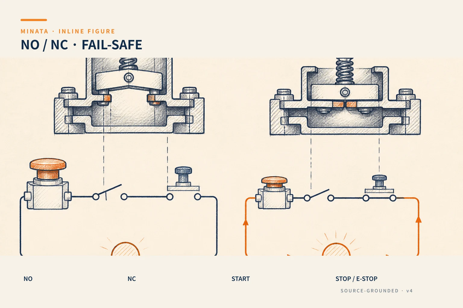

Reading NO/NC symbols on a drawing
On a circuit diagram the two contact types have different symbols and must be read correctly:
| Type | Common symbol | At rest | Note |
|---|
| NO | two bars with an open diagonal contact | Open (non-conducting) | Also called an "a contact" |
| NC | two bars with a diagonal bar across them | Closed (conducting) | Also called a "b contact" |
A key convention: a drawing always shows contacts at rest (de-energised / not actuated). When reading, ask yourself "is this device at rest or actuated?" and only then deduce whether the contact is closed or open. Skipping this step is the root of many faults during troubleshooting.
Terminal numbering also has a convention: many catalogues use pairs like 13-14 for a NO contact and 11-12 (or 21-22) for an NC contact. When wiring, follow the terminal numbers on the device and the terminal schedule — do not guess by wire colour.
Changeover contact (SPDT): NO and NC sharing a common
Besides separate NO and NC, a very common type on relays is the changeover contact (CO or SPDT). It has three terminals: a Common, an NO and an NC. At rest, the Common connects to NC; when actuated, the Common releases NC and switches to NO. The conventional numbering is often 11 (common) – 12 (NC) – 14 (NO).
A changeover contact is handy for "one of two": for example, when the relay is de-energised a yellow "waiting" light is on (via NC), and when energised a green "running" light is on (via NO) — using a single contact. But remember there is a very brief moment when both are open during the switch; do not design a circuit assuming NO and NC change state instantly and simultaneously.
On control relays and contactors, the auxiliary contacts also split into NO and NC by the same convention — this is what we use to build latching and interlock circuits in articles #11, #12 and #21.
The fail-safe principle: safe even when it fails
Every device fails one day: a broken wire, a loose ferrule, a worn contact, an oxidised connector. The right design question is “when it fails, does the machine fall to a safe or a dangerous state?” Designing so that a failure drives the system to a safe state is called fail-safe.
Consider a run-enable circuit passing through a stop button:
- If the Stop button is NC: normally the contact conducts, the circuit enables running. On a broken wire, loose ferrule or failed contact, the circuit opens → the run-enable signal is lost → the machine stops. The fault makes the machine safe by itself, and maintenance notices it immediately because the machine will not run.
- If (wrongly) the Stop button is NO: normally the contact is open… the logic is already wrong from the start. Worse, if the stop signal wire breaks, there is no way to stop anymore, and nobody knows.
That is why an almost unbreakable rule exists in the field: stop circuits and safety circuits use NC contacts, so loss of signal = stop.
Why Start is NO while Stop/E-stop are NC
Combining the two ideas above:
- The Start button is NO. Normally open, closing only when pressed to issue the run command. If the Start wire breaks, the result is cannot start — inconvenient but not dangerous. Conversely, if Start were NC, a short or a broken wire could create a false Start command, making the machine run on its own — which is not allowed.
- Stop and E-stop buttons are NC. Normally closed to "enable running". Pressing the button or a broken wire both open the circuit → stop. The failure leans toward safety.
For the E-stop, the standard also requires the contact to be of the direct/positive opening type — when pressed, the contact is mechanically forced open, not relying on a spring, so it still breaks even if the contact has welded (noted in article #09).

Bringing NO/NC into a PLC input
When signals enter the PLC, the NO/NC convention must keep its fail-safe spirit, with an added software layer:
- Input from a Start button: usually a NO contact. In the program, a rising edge of this signal triggers the run command.
- Input from a Stop button / safety circuit: a NC contact. Watch the inverted logic: because NC normally conducts, the PLC sees a logic 1 when "not stopped". In ST, the run-enable condition must be "the Stop signal is at 1 (circuit still closed)", and when the signal drops to 0 (Stop pressed or wire broken) the run state must be reset. Beginners often forget this inversion and write the logic backwards.
- The E-stop must not rely on the PLC alone. The E-stop circuit must break safely in hardware (through a safety relay or safety controller) first; the signal to the PLC is only for display and sequence coordination, not the sole protective layer.
- Contact bounce: a mechanical contact typically vibrates for a few milliseconds when opening/closing, creating a rapid 0-1-0 pulse train. For a hand-pressed button this is usually fine, but when used for counting or edge detection, filter the bounce with a settling time (a short timer in ST, or hardware filtering) so the PLC does not count one press as several.
A hardware coordination note: PLC inputs also distinguish sourcing (common positive) vs sinking (common negative) depending on the model. This does not change the NO/NC concept but decides whether the button group's common goes to +24 V or 0 V — check the input module documentation before wiring a whole row of buttons.
The table below summarises the choice:
| Signal | Contact type | On a broken wire | Why |
|---|
| Start | NO | Cannot start | Avoid a false run command |
| Stop | NC | Machine stops | Loss of signal = stop |
| E-stop | NC, positive opening | Machine stops | Human safety |
| Enabling sensor (door, guard) | NC | Treated as door open → stop | Fail-safe |
| Action confirm button | NO | Cannot confirm | Avoid a false confirmation |
A MINATA engineering reference
The illustration below is a reference approach following MINATA design thinking; final parameters and configuration must be confirmed against the actual records, standards and devices.
On a MINATA machine cell controlled by Delta AX-308E (CODESYS), the run-enable chain goes: control power → NC contact of the E-stop (positive opening) → NC contact of the safety-door sensor → coil of the safety relay. Only while this whole chain conducts does the safety relay close and power the drive section.
In parallel, the PLC reads the state of these contacts via inputs to display and coordinate the sequence: if it sees the door signal go to 0, it stops the cycle cleanly (no step jump) and turns on the corresponding indicator. Thus safety is guaranteed in hardware, while the PLC handles smooth operation. On any abnormality — a real button press or a broken wire — the machine leans toward stopping.
Common mistakes
- Wiring a Stop or E-stop as NO "to match Start" → losing fail-safe behaviour.
- Forgetting that the drawing shows contacts at rest, leading to reading conducting/open backwards.
- Writing PLC logic that forgets to invert the NC signal → a wrong run-enable condition.
- Treating the PLC as the sole safety layer for the E-stop, skipping the hardware safety circuit.
- Wiring by wire colour instead of the 13-14 / 11-12 terminal numbers printed on the device.
- Using a NO-type door sensor so that "loss of signal" is misread as "door safely closed".
NO/NC checklist
- [ ] Start and initiating commands: use NO.
- [ ] Stop, E-stop, safety sensors: use NC (loss of signal = stop).
- [ ] The E-stop uses positive-opening contacts and breaks safely in hardware.
- [ ] The PLC logic correctly inverts the NC signal in the run-enable condition.
- [ ] Wiring follows the device terminal numbers, matching the I/O list and terminal schedule.
- [ ] You have asked "does the machine stop or run on a broken wire?" for every critical signal.
Understanding NO/NC means getting used to the core question of safe design: when something fails, which way does the machine lean? — more than memorising two symbols. Answering that correctly for every signal lays the foundation for every control circuit that follows.
Read more automation knowledge at MINATA: https://minatavn.com/en/blog/industrial-automation
Previous — #09: Pushbuttons, selector switches and pilot lights: https://minatavn.com/en/blog/automation-09-pushbuttons-selectors-pilot-lights
Next — #11: Control relays: when they are needed and how to wire them: https://minatavn.com/en/blog/automation-11-control-relays
View all MINATA technical articles