Learn Automation with MINATA #11: Control Relays — When They Are Needed and How to Wire Them Correctly
Control relays: when they are needed and how to wire them correctly
A technician wires a 220 V solenoid valve coil straight to a PLC output because "it's a contact too, isn't it". A few weeks later that output dies, taking the whole module with it. A PLC output is made to issue a command, not to carry a load. Standing between those two roles is a small, cheap device found in almost every panel: the interposing (control) relay.
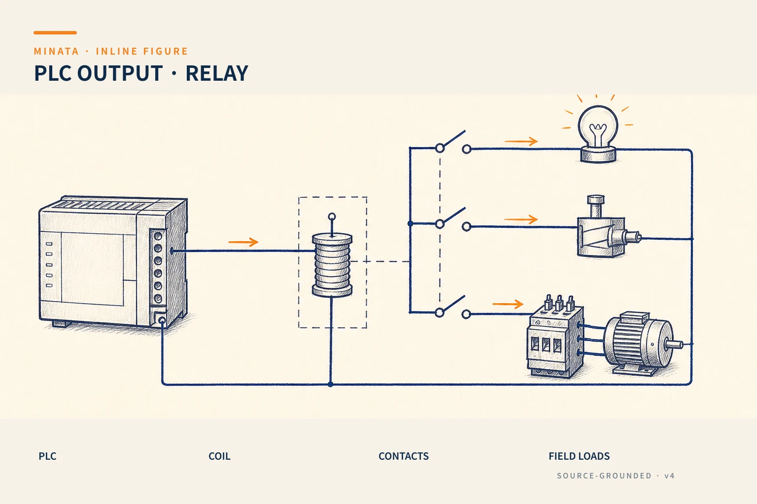
A control relay does nothing "clever". It is just a coil pulling a set of contacts. But that very simplicity solves four problems a PLC output should not handle itself: multiplying contacts, raising switching capacity, electrical isolation, and changing voltage level.
This article explains how a control relay works, the four reasons to use one, how to choose the coil and contacts, how to wire it, and why suppressing the reverse spike is mandatory when a coil works with a semiconductor output.
This article presents general principles. Specific ratings (coil voltage, contact current, insulation class) must follow the actual device catalogue and the standards applicable to the panel (for example IEC 60204-1).

What a control relay is
Structurally, a control relay consists of:
- Coil: when energised at its rated voltage (usually 24 VDC in a modern control panel, or 220 VAC), it creates a magnetic field that pulls the armature.
- Contacts: the armature moves the contacts between states — multi-pole types provide several NO, NC or changeover contacts each (see article #10).
- Socket and indicator LED: relays usually plug into a screw socket for easy replacement; many have an LED showing the coil is energised.
The key point: the coil control circuit and the circuit through the contacts are two electrically separate circuits. This is the basis for the isolation described below.

Four reasons to use a control relay
1. Multiply contacts. A PLC output is a single contact. When one command must act in several places (turn on a light, open a valve, signal another panel), a multi-pole relay allows "one command, many contacts" without using more outputs.
2. Raise switching capacity. PLC output contacts (especially the transistor type) carry very small currents, often a few hundred mA. Loads like large valve coils, sirens or incandescent lamps have high inrush current that easily exceeds this. Let the PLC output switch the relay coil (small current), and let the relay contact switch the load (larger current).
3. Galvanic isolation. Because coil and contacts are separate, a fault on the load side (short, overvoltage) hardly propagates back to the PLC. The control relay is a "buffer zone" protecting the expensive controller.
4. Change voltage/load level. The PLC works at 24 VDC, but many field loads are 220 VAC or another voltage. The relay coil takes 24 VDC from the PLC, while its contact switches a separate 220 VAC circuit — two voltage worlds meet safely through one device.
Distinguishing from a contactor
Beginners often confuse a control relay with a contactor. The practical boundary:
| Criterion | Control relay | Contactor |
|---|
| Task | Switch signals, small loads | Switch power loads (motors) |
| Contact current | Small (a few A) | Large (tens to hundreds of A) |
| Arc suppression | Basic | Dedicated arc chute |
| Utilization category | Mostly small resistive/inductive | AC-3 for motors (article #12) |
Rule: if the load is a motor or high power, use a contactor (article #12); otherwise — lights, valves, signals, interlocks — use a control relay.
Choosing a control relay
When choosing, mind four parameters:
- Coil voltage: match the control supply (prefer 24 VDC). Note it clearly on the drawing so a 220 V coil is never fitted into a 24 V circuit.
- Number of poles and contact type: 2 or 4 poles; each NO/NC/changeover. Choose a little spare for reserve contacts.
- Contact current and load type: rated current and utilization category (resistive differs from inductive). Inductive loads (valve coils, contactors) need derating versus resistive.
- Socket and accessories: screw or spring socket, integrated LED/diode module or not, retaining clip so the relay does not fall out under vibration.
Wiring and coil spike suppression
A relay coil is an inductive load. When power is cut abruptly, the collapsing magnetic field produces a very high reverse voltage spike in a short time. With a mechanical relay output, this spike causes arcing that wears the contacts. With a PLC transistor output, the reverse spike can destroy the semiconductor instantly.
So a suppression element must be fitted across the coil:
- Diode (for DC coils): mounted reverse-biased across the coil, clamping the spike. Cheap and effective, but makes the relay release slightly slower.
- RC snubber or varistor (MOV): for AC coils or when fast release is needed.
Many relay families have a plug-in diode/LED module — use it so it is not forgotten. Simple rule: an inductive coil next to a semiconductor must have a suppression element, no exceptions.
A few other wiring points:
- Number the terminals by device (A1/A2 for the coil; number pairs for contacts) and match the terminal schedule.
- Group relays in a row on the rail, with clear function labels.
- Add the relay coil currents to the load of the 24 VDC power supply (article #15).
Mechanical relays and solid-state relays (SSR)
Not every relay has mechanical contacts. There are two main families, chosen by switching frequency and load type:
- Electromechanical relay (EMR): the coil pulls a physical contact. Advantages: full isolation, very low voltage drop when conducting, switches both AC and DC, low cost. Disadvantages: contacts wear with switching cycles, an audible "click", slow transition (milliseconds), unsuited to high-frequency switching.
- Solid-state relay (SSR): uses semiconductors (triac/transistor) to switch, with no mechanical contact. Advantages: very fast and silent switching, very long life under continuous on/off (e.g. pulse temperature control), no arcing. Disadvantages: voltage drop and heat when conducting (usually needs a heatsink), small leakage current when "off", sensitive to overvoltage/overcurrent, and AC types differ from DC types.
Practical rule: infrequent switching, needing solid isolation and diverse loads → mechanical relay; frequent switching (temperature control, fast flashing) → SSR with proper heatsinking and protection.

Contact life and maintenance
For a mechanical relay, "life" has two different numbers — do not confuse them:
- Mechanical life: number of switching operations without load — usually very large (tens of millions).
- Electrical life: number of switching operations under load — much smaller and dependent on load type. Inductive loads (valve coils, contactors) wear the contacts faster than resistive loads because of arcing on break.
So when estimating durability, rely on electrical life at the correct load type, not the attractive mechanical figure in the catalogue. Habits that extend life: derate the contact for inductive loads, add a suppression element, avoid one relay switching too frequently, and use relays plugged into sockets to replace quickly when worn instead of removing a whole assembly. For continuous switching commands, consider an SSR from the design stage.
A MINATA engineering reference
The illustration below is a reference approach following MINATA design thinking; final parameters and configuration must be confirmed against the actual records, standards and devices.
On a cell using the Delta AX-308E, the outputs are not wired straight to the field but pass through a row of 24 VDC control relays on a DIN rail. Each output switches a relay coil that has a built-in suppression diode; the relay contact then goes out to a valve, a light, or a signal to another panel.
This gives three clear benefits: it protects the AX-308E output module from reverse spikes and load faults; when a field load fails, only one plug-in relay needs replacing instead of the whole PLC module; and it is easy to expand — need one more contact for a command, just use a free pole on the relay.
Other relay families common in panels
The "control relay" is the most common type, but a panel also holds a few specialised relay families that are easy to confuse — know them to choose the right one:
- Timer relay: switches a contact after a preset delay (on-delay, off-delay…). Used for star-delta starting and sequences with waits. Covered in article #25.
- Latching/impulse relay: holds its state after the coil loses power, toggling on a pulse — saving power and keeping state through an outage.
- Monitoring relay: watches for phase loss, phase sequence, over/undervoltage, level… and warns or trips on an abnormality. Very useful for protecting the incoming supply.
- Safety relay: a special type for E-stop/safety-door circuits, with positively-driven contacts and a redundant structure per safety standards — do not replace it with an ordinary control relay.
Common point: all still follow the NO/NC contact convention (article #10), but each solves a different problem. Do not use an ordinary control relay for the work of a safety or monitoring relay.
Common mistakes
- Wiring an inductive/220 V load straight to a PLC output, skipping the interposing relay.
- Forgetting the suppression diode/RC when a coil works with a transistor output.
- Fitting the wrong coil voltage (220 V into a 24 V circuit or vice versa).
- Using a control relay to switch a motor directly (that is a contactor's job).
- Choosing contacts exactly to need, with no reserve and no derating for inductive loads.
Control relay checklist
- [ ] The PLC output only switches a relay coil, not a heavy load.
- [ ] Coil voltage matches the control supply, noted clearly on the drawing.
- [ ] A diode/RC/varistor suppresses every inductive coil.
- [ ] Enough poles with spare; contacts derated for inductive loads.
- [ ] Relays plugged into sockets, labelled, with retaining clips against vibration.
- [ ] Relay coil currents added to the 24 VDC supply load.
The control relay is an "anonymous" device standing in a critical spot: between the controller and the real world. Placing it in the right place and wiring it correctly is how you protect the most expensive part of the panel.
Read more automation knowledge at MINATA: https://minatavn.com/en/blog/industrial-automation
Previous — #10: Normally-open and normally-closed contacts (NO/NC): https://minatavn.com/en/blog/automation-10-no-nc-contacts
Next — #12: Contactors: switching motors and power loads: https://minatavn.com/en/blog/automation-12-contactors
View all MINATA technical articles