Learn Automation with MINATA #12: Contactors — Switching Motors and Power Loads the Right Way
Contactors: switching motors and power loads the right way
A control panel for a 5.5 kW pump motor uses a contactor chosen by the current on the motor nameplate — surely that is enough. After a few months of continuous switching, the main contacts are pitted and welded, and the motor sometimes loses a phase without anyone noticing. The cause: whoever chose it looked at the rated current but ignored the utilization category — a contactor switching a motor must withstand a starting current 6–8 times the rated current, an entirely different requirement from switching a resistive load.
A contactor is the device that switches power circuits — where large currents feed motors, heaters, capacitor banks. It resembles a control relay in the "coil pulls contacts" principle, but differs entirely in scale: large contacts, an arc-suppression chamber, and classification by the load type it serves.
This article covers contactor construction, distinguishing main from auxiliary contacts, the meaning of utilization categories AC-1 / AC-3, how to build the motor-start latching circuit, and how to choose a contactor correctly.
This article presents principles. Overload protection for a motor is the subject of article #13 (thermal relay); short-circuit protection is article #14 (breaker/fuse). Ratings must follow the actual catalogue and applicable standards (for example IEC 60947-4-1 for contactors and motor starters).

Construction: main contacts, auxiliary contacts and coil
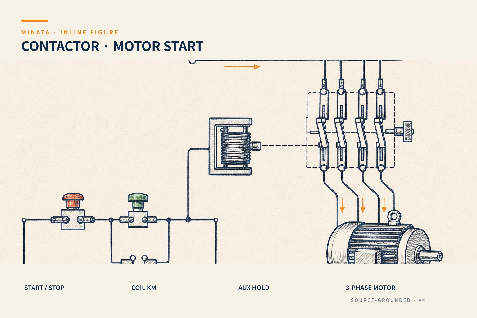
A typical contactor consists of:
- Coil (A1-A2): energised at its rated voltage (24 VDC, 220 VAC or 380 VAC depending on type) it pulls the armature and closes the contacts.
- Main contacts: usually 3 poles for a three-phase motor (numbered 1-2, 3-4, 5-6 or L1-T1…). These are large contacts carrying large current, with an arc-suppression chamber to quench the spark when breaking an inductive load.
- Auxiliary contacts: small, used for the control circuit — status signalling, latching, interlock. Some are integrated as 1 NO + 1 NC, others add an auxiliary block on top.
Point to remember: main contacts switch the load, auxiliary contacts do the logic. Do not use auxiliary contacts to switch a motor, nor take main contacts to make a control signal.
Many contactors also accept an add-on auxiliary contact block or mechanical block (mechanical interlock, pneumatic timer) mounted on the side or top. So one contactor family can build many circuits — from simple starting to reversing and star-delta — without changing the main device. When designing, leave spare auxiliary contacts for logic needs that arise later.

Utilization category: why AC-3 differs from AC-1
This is the most important and most often overlooked concept. The utilization category describes the load type and switching conditions the contacts must withstand:
| Category | Load type | Switching characteristic |
|---|
| AC-1 | Resistive or lightly inductive (heaters, cos φ ≥ 0.95) | Switching current ≈ rated current |
| AC-3 | Squirrel-cage motor, break while running | Making current 6–8× rated (starting current) |
| AC-4 | Motor reversing/jogging, break before full speed | Harshest, breaking current still very high |
Practical consequence: a contactor rated "40 A per AC-1" may only withstand about 18–25 A per AC-3. If you choose a contactor for a motor by the impressive AC-1 number, the contacts wear quickly because they actually carry a much larger starting current. For a motor, read the AC-3 current, not AC-1.
The motor-start latching circuit
The classic "Start-Stop" circuit of a motor uses exactly the components already learned:
- A Stop button wired NC, in series in the circuit — a broken wire or a Stop press both break it (fail-safe, article #10).
- A Start button wired NO, pressed to energise the contactor coil KM.
- A NO auxiliary contact of KM in parallel with the Start button. When KM pulls in, this auxiliary contact closes and self-holds current to the coil even after Start is released.
- Pressing Stop (or a power loss, or the thermal relay tripping) → coil KM loses power → everything releases → the motor stops.
This is the latching circuit article #09 mentioned in its PLC version; here it is built purely from electromechanical devices. Understanding this circuit is understanding the backbone of traditional motor control — and the basis for reading reversing and star-delta diagrams in articles #23, #24.
Choosing a contactor
Practical steps:
- Identify the load: motor kW, voltage, rated current (read the motor nameplate).
- Choose by AC-3: take the contactor's AC-3 current ≥ the motor rated current, with margin. For reversing/jogging loads, consider AC-4 or derating.
- Choose the coil voltage: match the control circuit (24 VDC or 220 VAC). Note it on the drawing.
- Auxiliary contacts: enough for self-holding + status + interlock; add an auxiliary block if short.
- Coordinate protection: the contactor goes with a thermal relay (overload, article #13) and a breaker/fuse (short circuit, article #14) to form a complete motor starter. These three devices coordinate with each other; they are not chosen in isolation.
Coil voltage: AC or DC
Contactor coils come in AC (usually 220 VAC or 380 VAC) and DC (24 VDC) types. The difference is not just the voltage number:
- AC coil: has an inrush current several times the holding current when first closing, and produces a hum if the core is dirty or the voltage low. If the coil supply sags (long wires, many loads closing together), the coil may pull in indecisively and the contacts chatter — very harmful. Ensure the voltage at the coil stays within the allowed band (usually 85–110% of rated).
- DC coil: steady current, no hum, suited to control from a 24 VDC PLC/relay, but produces a reverse spike on break so it needs a suppression element (as in article #11). For large contactors, makers often integrate an electronic control module to reduce holding power.
Rule: standardise the control level across the whole panel (prefer modern 24 VDC), note the coil voltage on the drawing, and check the voltage sag when many coils close at once.
Reading the nameplate on a contactor
When holding a contactor, the most important numbers on the label:
- Ie / AC-3 (at voltage Ue): rated operating current per AC-3 — the number to choose for a motor. Usually shown with the corresponding motor power (kW) at each voltage.
- Ith / AC-1: thermal (resistive) current — larger, do not use for a motor.
- Ui, Uimp: rated insulation voltage and impulse withstand — related to insulation safety.
- Coil voltage (A1-A2): as above.
- Number of main poles and integrated auxiliary contacts (e.g. 3P + 1NO or 3P + 1NO1NC).
Reading the "motor power by voltage" table on the body/catalogue correctly is the fast, safe way to choose: look up the motor kW at the actual mains voltage and get the right model directly, without converting by hand.

When several contactors are needed: reversing and star-delta
Some motor circuits need more than one contactor, which is why one must understand a single contactor well first:
- Reversing: uses two contactors — one for forward, one swapping two of the three phases to run reverse. A mechanical/electrical interlock is mandatory so the two never close together (causing a phase-to-phase short). The interlock is made with a NC auxiliary contact of one in series with the other's coil circuit, and/or a mechanical lock. Details in article #23.
- Star-delta starting: reduces the starting current of a large motor with three contactors (main, star, delta) switching the wiring from star to delta after a few seconds, coordinated with a timer relay. Details in article #24.
Common point of these circuits: they are just several contactors coordinated by the same latching and interlock circuits already learned. Master a single contactor and you can read the more complex diagrams.
A MINATA engineering reference
The illustration below is a reference approach following MINATA design thinking; final parameters and configuration must be confirmed against the actual records, standards and devices.
On a MINATA conveyor cell, a three-phase motor is switched by a contactor chosen per AC-3. The Delta AX-308E output does not close the high-voltage contactor coil directly but passes through a 24 VDC control relay (article #11); the relay contact then feeds the contactor coil. This isolates the PLC from the power circuit.
A NO auxiliary contact of the contactor is brought back to a PLC input to confirm "the contactor has actually closed" — following the principle from article #09 of taking lights/status from real feedback, rather than trusting that issuing a command means the motor is running. If the PLC issues the command but does not see the auxiliary contact close, it raises a fault instead of continuing the cycle.
Common mistakes
- Choosing a contactor by the AC-1 current for a motor load → contacts wear fast and weld.
- Using auxiliary contacts to switch the motor, or taking main contacts as a control signal.
- Omitting the latching circuit, forcing the operator to hold the Start button.
- Choosing the contactor in isolation, not coordinated with the thermal relay and breaker.
- Wiring a 220 V/380 V contactor coil straight to a PLC output instead of via a control relay.
- Forgetting to report the auxiliary contact back to the PLC to confirm the real state.
Contactor checklist
- [ ] Current chosen per AC-3 (motor), with margin.
- [ ] Coil voltage matches the control circuit, noted on the drawing.
- [ ] The latching circuit uses a NO auxiliary contact of the contactor itself.
- [ ] Stop and the safety circuit are NC, in series in the control circuit.
- [ ] Enough auxiliary contacts for self-holding, interlock, status.
- [ ] Coordinated with the thermal relay (#13) and breaker/fuse (#14).
- [ ] An auxiliary contact reports back to the PLC to confirm closure.
The contactor is where the "small" control circuit commands the "large" power circuit. Choosing the right utilization category and building the right latching circuit lays a solid foundation for every motor starter that follows.
Read more automation knowledge at MINATA: https://minatavn.com/en/blog/industrial-automation
Previous — #11: Control relays: when they are needed and how to wire them: https://minatavn.com/en/blog/automation-11-control-relays
Next — #13: Thermal overload relays: protecting the motor from overload: https://minatavn.com/en/blog/automation-13-thermal-overload-relays
View all MINATA technical articles