Learn Automation with MINATA #13: Thermal Overload Relays — Protecting the Motor from Prolonged Overload
Thermal overload relays: protecting the motor from prolonged overload
A motor driving a conveyor jams on some material, and the current rises to about 1.3 times rated. Not enough for the breaker to trip — a breaker only catches short circuits and very large overloads. That current smoulders on, the motor windings heat up, the insulation ages fast, and a few weeks later the motor burns out. The device that should have caught this is a dedicated one: the thermal overload relay.
The boundary is important and often blurred: a breaker/fuse protects against a short circuit (very large current, instantaneous trip), while a thermal relay protects against an overload (a slightly high current, prolonged). Two different fault types need two different devices; neither replaces the other.
This article explains how a thermal relay works, why it trips on an inverse-time characteristic, the meaning of class 10/20/30, how to set the current by the motor's FLA, and how to wire the contacts to drop the contactor.
This article presents principles. Ratings must follow the device catalogue and applicable standards (for example IEC 60947-4-1 for motor starters). For important motors, an electronic protection relay can replace the bimetallic thermal relay.

Principle: bimetal and accumulated heat
The classic thermal relay relies on a bimetal strip — two metals of different expansion coefficients bonded together. The motor current passes through (or through a heater coil around the bimetal); the higher the current, the hotter the bimetal gets and the more it bends. When the bend is large enough, it trips a mechanical latch, changing the state of the contact set.
The beauty of this mechanism is that it mimics how a motor actually heats up: heat accumulates over time, not instantly. A slightly high current over a long time is dangerous; a brief high current (like the starting current) is not. The bimetal "remembers heat" just like the motor windings, so it protects without nuisance-tripping at start.
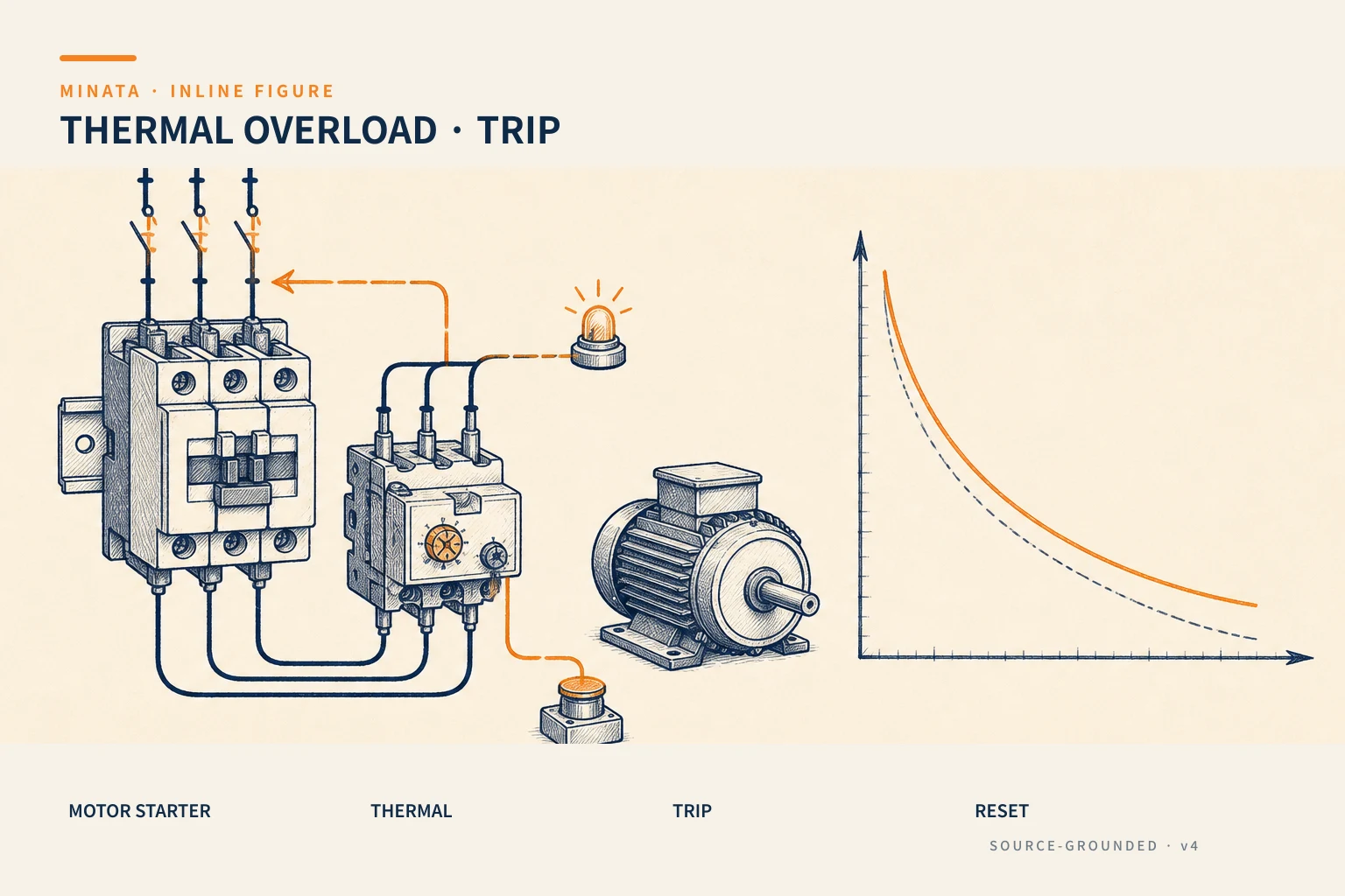

The inverse-time characteristic
This is the core property: the higher the current, the shorter the trip time (inverse time). At a current just over rated, the relay waits quite a while before tripping; at several times rated, it trips much faster. The characteristic curve slopes down as in the figure.
Thanks to this, the thermal relay does not trip during starting: a squirrel-cage motor starts with a current 6–8 times rated but only for a few seconds, staying below the curve so the relay "ignores" it. But if that starting current lasts abnormally long (the motor cannot turn, the load is jammed), the time exceeds the threshold and the relay trips.
Class 10, 20, 30: how long it withstands starting
The class (tripping class) tells how long the relay withstands 7.2 times rated current before tripping:
| Class | Trip time at 7.2× I | Used for |
|---|
| Class 10 | ≤ 10 s | Light, quick starting motors (pumps, small fans) |
| Class 20 | ≤ 20 s | Medium starting, moderate inertia loads |
| Class 30 | ≤ 30 s | Heavy starting, high inertia (compressors, heavy conveyors) |
Choosing too low a class for a heavy-starting load → the relay trips right at start and the machine cannot run. Choosing too high for a light load → weak, insensitive protection. Class 10 is the common default; raise it when starting takes longer.
Setting the current and wiring the contacts
- Set the current to FLA: the thermal relay has a current-range dial. Set it exactly to the Full Load Ampere (FLA) on the motor nameplate. Set too high and protection is lost; too low and it nuisance-trips.
- Auxiliary contacts: the thermal relay usually has one NC contact (95-96) and one NO (97-98). The NC 95-96 is in series in the contactor coil circuit; on overload it opens → coil KM loses power → the motor stops. The NO 97-98 is for fault signalling (light/PLC).
- Reset mode: choose manual reset for important motors (forcing a check before restart) or auto reset where appropriate. For safety, manual reset is usually preferred.
- Mounting position: the thermal relay mounts right after the contactor, on the line to the motor, to measure the actual motor current. Many thermal relays are designed to plug directly onto the output terminals of the same-brand contactor, forming a compact block — saving space and ensuring the current passes through all three motor phases correctly. When using a separate block, bridge in the correct phase order, not misaligned.
- All three phases must pass through: the thermal relay measures the current of all three phases; if for some reason only two phases pass (miswired), its ability to detect overload and phase loss is skewed.
Note: a thermal relay does not protect against a short circuit. A very large short-circuit current would damage the relay itself before the bimetal could react — that is the breaker/fuse's job (article #14). The three devices (breaker – contactor – thermal relay) must coordinate.
Bimetal, temperature compensation and phase-loss protection
A few practical characteristics to use a thermal relay correctly:
- Ambient temperature compensation: the bimetal reacts to heat, so the panel temperature also affects it. A good thermal relay has a compensation mechanism so the trip threshold does not drift too much when the panel is hot. Even so, an overly hot panel makes the relay more sensitive than intended — panel ventilation/cooling is part of motor protection.
- Phase-loss protection: when a three-phase motor loses one phase, the remaining two phases increase current and the motor easily burns. Many thermal relays have a differential phase-loss mechanism — tripping faster when the three phases become unbalanced, rather than waiting for the ordinary overload threshold. For important motors, choose a type with this feature.
- Cooling and reset: after tripping, the bimetal needs time to cool before it can reset — do not reset repeatedly. Resetting too soon while the motor is still hot forces it into an overheating spiral.
Bimetallic thermal relay and electronic protection relay
Beside the classic bimetallic type, there is also an electronic motor protection relay/block (electronic overload):
| Criterion | Bimetallic | Electronic |
|---|
| Principle | Thermo-mechanical | Current sensing + processing |
| Accuracy | Fair | High, wide setting range |
| Features | Basic | Phase loss, rotor lock, phase imbalance, event log, communication |
| Cost | Cheap | Higher |
For most machines, the bimetallic thermal relay is sufficient and economical. For expensive motors, continuous duty, or remote monitoring needs, the electronic protection block (often integrated into a communication network to report to a PLC/SCADA) is worth the investment.

A concrete current-setting example
Suppose a three-phase 380 V motor shows FLA = 7.5 A on the nameplate, light starting. How to set:
- Choose a thermal relay with a range covering 7.5 A — for example a 5.5–8 A range. Do not choose 4–6 A (does not reach) or 9–13 A (7.5 A sits near the bottom, imprecise to set).
- Set the dial exactly to 7.5 A, not rounded up "to avoid tripping".
- Choose class 10 (light starting). For a heavy, high-inertia conveyor, consider class 20.
- Choose the contactor per AC-3 ≥ 7.5 A (article #12) and a breaker/fuse for short-circuit protection (article #14) coordinated with it.
If after fitting the relay it still trips at start, check in order: is the current set to the correct FLA → is the class suited to the starting time → is the motor jammed/phase-imbalanced. Do not "fix" it by turning the current up — that abandons protection.
Avoiding nuisance trips and restarting too soon
Two operational mistakes common with thermal relays:
- Nuisance tripping on many consecutive restarts: each start injects heat into the motor and the bimetal; rapid consecutive starts leave heat no time to dissipate. If the process needs many starts per hour, account for this when choosing the motor and class.
- Resetting while the motor is still hot: as said, the bimetal needs to cool before resetting. Forcing a restart just after tripping pushes the motor into an overheating spiral. For important motors, use manual reset to force the operator to stop and check the cause before running again.
A MINATA engineering reference
The illustration below is a reference approach following MINATA design thinking; final parameters and configuration must be confirmed against the actual records, standards and devices.
On a MINATA cell, each motor uses the classic trio: breaker (short circuit) → contactor (switching) → thermal relay (overload) → motor. The NC 95-96 contact of the thermal relay sits in series in the contactor coil circuit, so on overload the motor stops in hardware without needing the PLC.
In parallel, the NO 97-98 contact is brought to a Delta AX-308E input so the PLC knows "this motor just overloaded" — turning on the corresponding red light, logging the event and cleanly stopping the running cycle. The operator immediately sees which motor faulted instead of opening the panel to check each relay. After handling the cause, they manually reset the thermal relay before restarting.
Common mistakes
- Confusing the thermal relay with the breaker, thinking one device covers both overload and short circuit.
- Setting the thermal relay current above FLA "to avoid tripping" → losing protection.
- Choosing a low class for a heavy-starting load → nuisance-tripping at start.
- Forgetting to wire the NC 95-96 contact into the contactor coil circuit → the relay trips but the motor keeps running.
- Using auto reset on a dangerous motor, letting the machine restart itself after a fault.
- Not signalling the fault (97-98) to the PLC/light, making it hard to know which motor overloaded.
Thermal relay checklist
- [ ] Understand clearly: the thermal relay handles overload, the breaker/fuse handles short circuit.
- [ ] Set the current exactly to the FLA on the motor nameplate.
- [ ] Choose a class suited to the load's starting time.
- [ ] The NC 95-96 contact is in series in the contactor coil circuit.
- [ ] The NO 97-98 contact signals the fault to a light/PLC.
- [ ] Choose the reset mode (prefer manual for important motors).
- [ ] Coordinated with the contactor (#12) and breaker (#14) into a complete starter.
The thermal relay is the "heat guardian" for a motor: it does not react to instantaneous faults, but catches exactly the smouldering overload most likely to kill a motor. Setting the right current and wiring the right contacts extends the life of the most expensive part of the drive assembly.
Read more automation knowledge at MINATA: https://minatavn.com/en/blog/industrial-automation
Previous — #12: Contactors: switching motors and power loads: https://minatavn.com/en/blog/automation-12-contactors
Next — #14: Fuses and circuit breakers: short-circuit and overcurrent protection: https://minatavn.com/en/blog/automation-14-fuses-circuit-breakers
View all MINATA technical articles