Learn Automation with MINATA #14: Fuses and Circuit Breakers — Short-Circuit and Overcurrent Protection
Fuses and Circuit Breakers: Short-Circuit and Overcurrent Protection
Two busbars in the panel touch through a screw that has worked loose. In an instant the current shoots up to thousands of amps — enough to blow apart equipment, burn wiring and throw a dangerous arc at anyone standing nearby. The only thing between that fault and disaster is the upstream device: a fuse or a circuit breaker. And if that device has a breaking capacity lower than the actual short-circuit current, it too explodes when it tries to interrupt.
This is the last line of defence and, in safety terms, the most important. In #13 we drew the line clearly: the thermal relay handles overload — a slightly high current, sustained. This article handles the rest: short circuit (an enormous, instantaneous current) and large overcurrent, the job of fuses and circuit breakers.
This article distinguishes fuses from circuit breakers, explains the two mechanisms — thermal and magnetic — inside a breaker, the meaning of the B/C/D curves, the vital concept of breaking capacity (Icu/Icn), and how protection is coordinated inside a panel.
This article states principles. Calculating the short-circuit current, choosing the breaking capacity and arranging selectivity must follow a real electrical-system calculation and the applicable standards (for example IEC 60947-2 for circuit breakers, IEC 60269 for fuses).

How a short circuit differs from an overload
Two kinds of current fault, two different natures:
- Overload: current a little above rated (say 1.2–2×), sustained. Dangerous because accumulated heat destroys the insulation. → handled by the thermal relay (#13).
- Short circuit: phase conductors touch each other or touch earth, the impedance is nearly zero, and the current jumps to hundreds or thousands of times rated in a fraction of a second. The danger is instantaneous: explosion, fire, arc. → the fuse/breaker must interrupt almost immediately.
A good device has to tell these two situations apart, so it does not trip wrongly on a starting inrush (a brief high current) yet interrupts at once on a genuine short circuit.

The fuse: simple, fast, single-use
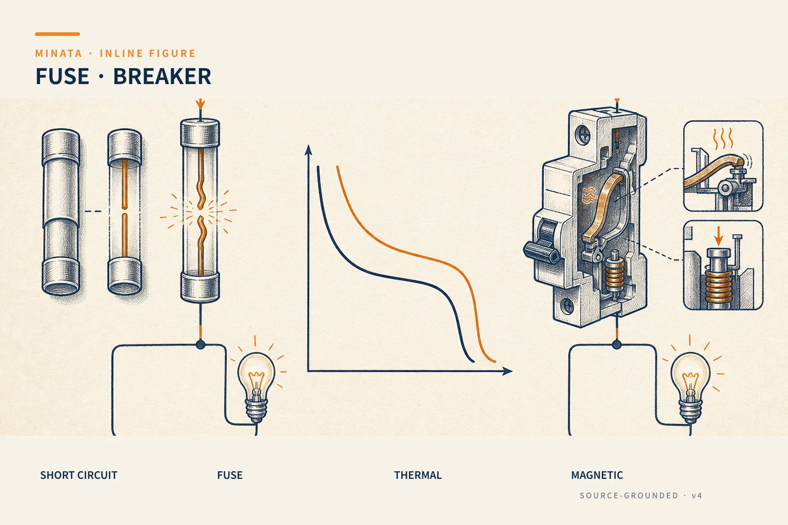
A fuse is a fusible element in a housing. When the current exceeds the threshold for long enough (or on an instantaneous short circuit), the element melts and opens, breaking the circuit.
- Strengths: extremely fast on a large short-circuit current, high breaking capacity, simple, cheap, no mechanism to fail.
- Weaknesses: once blown it is replaced, not reset; when one phase blows it can leave a motor single-phasing; recovery takes longer, since you need the correct spare on hand.
Fuses are still very common upstream where a very high breaking capacity is needed, or for protecting semiconductors (ultra-fast fuses for VFDs).
The circuit breaker: two mechanisms in one
A circuit breaker (MCB — miniature, MCCB — moulded-case, larger) combines two tripping mechanisms in one resettable device:
- Thermal mechanism: a bimetal strip, like the thermal relay, trips on an inverse-time characteristic against overload current. The higher the current, the faster it trips.
- Magnetic mechanism: an electromagnetic coil trips almost instantaneously when the current exceeds a high threshold (short circuit). This is the "vertical zone" on the characteristic curve.
Thanks to the two mechanisms, a single breaker handles both overload and short circuit, and you simply flip it back on after clearing the fault — far more convenient than a fuse. This is why MCBs/MCCBs dominate the modern panel.
The B, C, D curves: choosing the magnetic threshold
The main difference between MCB types is the current threshold that trips the magnetic mechanism, denoted by a letter:
| Type | Magnetic (instantaneous) trip threshold | Used for |
|---|
| B | 3–5 × In | Resistive loads, lighting, sockets — low starting current |
| C | 5–10 × In | Mixed loads, small motors, moderate inductive loads |
| D | 10–20 × In | High-inrush loads (large motors, transformers, capacitors) |
Choosing the wrong curve is the root of "the breaker keeps tripping when I start the machine": use a type B for a motor whose starting current is 8× rated and the magnetic mechanism mistakes the inrush for a short circuit and trips. For high-inrush loads, choose C or D.
Breaking capacity (Icu/Icn): the most overlooked spec
This is the number that decides safety yet is often forgotten: the short-circuit breaking capacity — the largest short-circuit current the breaker can interrupt safely, in kA. Marked Icu (ultimate breaking capacity) and Icn/Ics on the label.
The mandatory rule: Icu must be ≥ the prospective short-circuit current at the point of installation. If a 10kA short circuit is possible at the panel but the breaker is rated only 6kA, then on a real short circuit the breaker itself explodes instead of interrupting safely — turning the protective device into a source of danger. The prospective short-circuit current depends on the source/transformer capacity and the line impedance; it must be calculated, not guessed.
Coordinating protection in the panel
Breakers and fuses do not stand alone. They sit in a coordinated chain:
- With a motor starter: the breaker (or fuse) handles the short circuit → the contactor switches (#12) → the thermal relay handles the overload (#13). The three devices are chosen in coordination (type 1 / type 2 coordination) so that damage is limited on a short circuit.
- Selectivity: on a fault in one branch, only that branch's breaker trips and the upstream main breaker stays closed, so the whole panel is not shut down. This is achieved by grading currents and characteristics sensibly.
- Conductor cross-section: the breaker must protect the wire downstream of it — its rated current must not exceed the wire's current-carrying capacity, or the wire burns before the breaker trips.
The family: MCB, MCCB, RCCB, RCBO
Within the breaker family there are a few common types — do not confuse their jobs:
| Type | Main job | Note |
|---|
| MCB | Short circuit + overload, small currents | Miniature, rail-mounted, common on branches |
| MCCB | Short circuit + overload, large currents | Moulded-case, some with adjustable thresholds |
| RCCB (RCD) | Earth-leakage current | Does not protect against overload/short circuit |
| RCBO | MCB + RCCB combined | Both overcurrent and leakage |
Key point: an RCCB/RCD protects people from electric shock and prevents fires from leakage; it does not replace an MCB. It compares the outgoing and returning current; a difference beyond the threshold (for example 30mA for personnel protection) trips it. To get both functions in one rail-mounted device, use an RCBO.

Earth-leakage and earth-fault protection
A phase-to-phase or phase-to-neutral short is usually caught by the breaker. But an earth-leakage current (degraded insulation, a person touching a live part) can be smaller than the MCB's trip threshold yet still enough to be lethal or to generate fire-starting heat. This is why a residual-current device (RCD/RCBO) is needed on circuits with a contact risk.
Common thresholds: 30mA for shock protection (socket circuits, hand-held equipment), 100–300mA for fire protection against leakage on power circuits. With a VFD, high-frequency leakage current can nuisance-trip an ordinary RCD — in that case choose a type B RCD suited to the drive. Whether an RCD/RCBO is required, and at what threshold, must follow the assessment and the applicable installation standard.
Choosing the rated current: between load and wire
The breaker's rated current In must sit within a valid "window":
- Not below the load's working current (plus a sensible margin) — otherwise the breaker trips under normal load.
- Not above the current-carrying capacity of the wire downstream — otherwise the wire can overheat and burn before the breaker trips. A breaker exists partly to protect the conductor, so it must be chosen together with the wire cross-section.
A simple example: a branch load working at ~12A, run on wire rated ~20A, makes a 16A type-C MCB reasonable — above the working load, below the wire's capacity. If for some reason it must go up to 25A, the wire cross-section has to rise accordingly. This "breaker ↔ wire" pair always goes together, never apart.
For a motor, the branch rated current is further coordinated with the thermal relay and contactor per the manufacturer's selection tables, rather than sizing each in isolation.
A reference engineering scenario
The illustration below is a reference approach in the spirit of MINATA's design thinking; the final ratings and configuration must be confirmed against the actual documentation, standards and equipment.
In a MINATA control panel, the incomer is a main MCCB whose Icu is chosen for the prospective short-circuit current at the connection point. From the busbar the branches divide: a power branch for each motor (type C/D MCB + contactor + thermal relay), a 24VDC control-power branch (a small type B MCB protecting the power supply), and a branch feeding the Delta AX-308E and its modules.
This grading gives two benefits: on a motor short circuit, only that branch's MCB trips while the PLC and the other branches keep running for an orderly stop; and every wire in the panel is protected by a breaker of the right rating, with no length of conductor left "bare" before a fault. The status of important breakers can be brought back to the PLC through an auxiliary contact to warn when one has tripped.
Common mistakes
- Confusing the roles: assuming the breaker/fuse protects a motor against overload as well as the thermal relay does.
- Ignoring the Icu breaking capacity → the breaker explodes on a real short circuit.
- Using a type B curve for a high-inrush motor load → tripping on start.
- Choosing a breaker current higher than the current-carrying capacity of the wire downstream.
- No selectivity → a single branch fault trips the whole panel.
- Replacing a blown fuse with the wrong current or characteristic "just to have one" when the spare runs out.
Fuse / circuit-breaker checklist
- [ ] Distinguish clearly: short circuit (this device) vs overload (thermal relay).
- [ ] Icu/Icn ≥ prospective short-circuit current at the point of installation.
- [ ] The curve (B/C/D) suits the load's starting current.
- [ ] The rated current protects the wire cross-section downstream.
- [ ] Coordinated with the contactor (#12) and thermal relay (#13) for the starter.
- [ ] Selectivity between the main and the branch breakers.
- [ ] The correct spare fuse (right type, right current) is always on hand.
Fuses and circuit breakers are the line of defence that meets the harshest situation in the panel. Choosing the right breaking capacity and the right curve is the line between a device that interrupts safely and a device that becomes the source of an accident.
Read more automation knowledge at MINATA: https://minatavn.com/en/blog/industrial-automation
Previous — #13: Thermal overload relays: protecting the motor from prolonged overload: https://minatavn.com/en/blog/automation-13-thermal-overload-relays
Next — #15: 24VDC power supplies: sizing and calculation for control panels: https://minatavn.com/en/blog/automation-15-24vdc-power-supply
View all MINATA technical articles