Learn Automation with MINATA #15: 24VDC Power Supplies — Sizing and Calculation for Control Panels
24VDC Power Supplies: Sizing and Calculation for Control Panels
A control panel runs steadily for months, then starts "acting up": now and then the PLC resets, a sensor reads erratically, the HMI flickers. Swapping the PLC and the sensors changes nothing. The culprit turns out to be a 24VDC power supply chosen right at the limit: when the valves and lamps switch on together, the current surges past the supply's rating, the voltage sags below threshold, and the whole panel "starves" at once. The supply is not truly broken — it simply is not strong enough.
The 24VDC supply is the electrical heart of a modern automation panel: the PLC, sensors, relay coils, solenoid valves and HMI nearly all run on 24VDC. Choosing the wrong capacity, wiring carelessly or skipping margin does not cause an immediate failure — it creates the hardest-to-find intermittent faults.
This article explains why 24VDC became the standard, how to choose the supply type, how to total the load and add margin, what to watch for with inrush current, how to protect, wire and earth it, and redundancy options for important machines.
This article states principles. Specific ratings must follow the power-supply catalogue and the standards applicable to the panel (for example IEC 60204-1). The 0V earthing method follows the manufacturer's guidance and the installation rules.

Why 24VDC became the standard
24VDC won out in industrial control because it balances three things:
- Safety: 24V is in the extra-low-voltage (ELV) band, far safer than 220V to work on and wire.
- Strong enough to reach: higher than 12V, so it tolerates the voltage drop over long runs inside the panel and out to the field while keeping the signal stable.
- A ready ecosystem: nearly every PLC, sensor, relay, valve and HMI has a 24VDC version — using one voltage keeps the panel compact and easy to maintain.
For those reasons the modern control circuit defaults to 24VDC; 220VAC remains only on the power circuit and a few large contactor coils.

Supply types: linear and switch-mode (SMPS)
Two main families:
- Linear supplies: a bulky transformer, low efficiency, hot, heavy. Rare in panels today, left only in a few applications needing very low noise.
- Switch-mode supplies (SMPS): compact, high efficiency, DIN-rail mounted, wide input range. This is the default for automation panels. Choose one with an input range that suits the mains (for example 85–264VAC), with overload/short-circuit/over-temperature protection and a status indicator.
Some SMPS have a "power boost" characteristic — tolerating a brief overload to overcome inrush; very useful when a load has a high current peak.
Totalling the load and adding margin
This is the decisive step. The rule: add up the current draw of every 24V load, then add 25–30% margin.
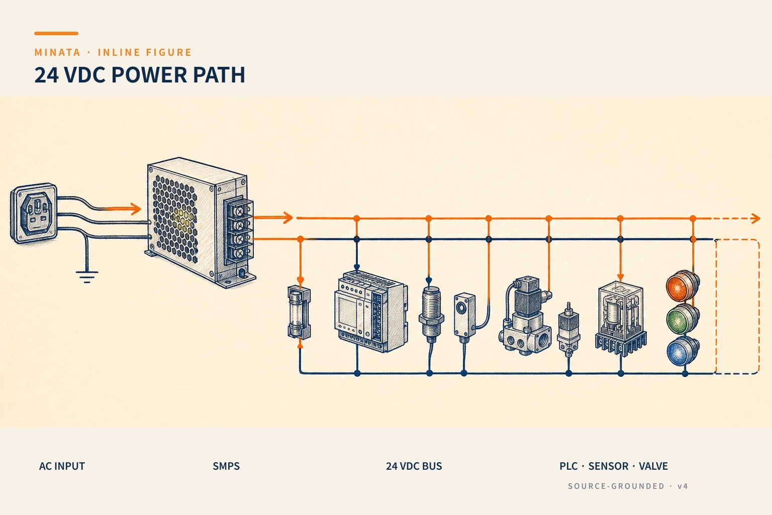
For a small panel like the one in the figure:
| Load | Current (A) |
|---|
| PLC CPU + I/O (AX-308E) | 1.5 |
| Sensors (photoelectric/proximity) | 1.0 |
| Relay coils / solenoid valves | 2.0 |
| HMI + pilot lights | 0.8 |
| Total | 5.3 |
Add 30% margin: 5.3 × 1.3 ≈ 6.9A → choose a supply ≥ 7A, in practice usually rounded up to a 24V/10A supply for comfort and room to expand.
Why the margin is needed: (1) the paper calculation often misses small loads; (2) the load grows as equipment is added later; (3) running near 100% keeps the supply hot, shortens its life and makes it sag at peaks. Do not choose a supply that just fits the total.
Inrush current — the trap that is often missed
Many loads draw a peak current at switch-on higher than their steady running current:
- Solenoid valves and relay coils: a current peak on pull-in.
- Lamps (especially incandescent) and capacitive loads: a large initial charging peak.
- Some modules with input capacitors: charging the capacitor creates a brief current peak.
If many loads switch on at once, the combined peak can far exceed the average total current. An under-sized supply sags for an instant, upsetting the PLC/sensors. The remedy: choose a supply with margin and peak capability, or sequence the loads to switch on staggered rather than all together.
A subtle point: when a supply meets a transient overload it usually behaves in one of two ways — "hiccup" (retrying repeatedly) or "constant current" (holding current, dropping voltage). For a load with a starting peak, constant-current or power-boost behaviour suits better, because a hiccup mode can leave the supply pulsing and unable to start the load. Read the supply's overload characteristic carefully for "difficult" loads.
Branch protection, wiring and earthing
- Split the 24V branches: do not run every load off one line. Divide into branches (PLC, sensors, valves…) and protect each with a small fuse or breaker, or a protected distribution module. When one branch shorts, only that branch opens and the rest keeps running for an orderly stop.
- AC input of the supply: fed through its own MCB for switching and protection.
- Clear +24V and 0V wiring: consistent conventional colours, cross-section adequate for the current and voltage drop; avoid undersized wire on long runs.
- 0V earthing: many systems earth 0V at a single point per the maker's guidance for noise immunity and a stable reference. Do it by the documentation, not at several arbitrary points that create earth loops.
Reading the specs when buying a supply
Beyond output current, a few label/catalogue specs are worth attention:
- Output voltage and adjustment range: most industrial SMPS allow a small output-voltage trim (for example 24–28V). You can nudge it up a little to offset drop on a long run, but do not exceed the load's permitted range.
- Input voltage range: choose a wide range (e.g. 85–264VAC) so mains fluctuation is not a worry; where the supply is weak, this matters a lot.
- Efficiency and heat: high efficiency runs cooler and needs less cooling space in the panel. The hotter the supply, the shorter its life — leave ventilation clearance around it per the guidance.
- Hold-up time: how long the supply keeps 24V after the input fails; relates to riding through a brief mains dip.
- Built-in protection: overload (usually self-recovering), short circuit, over-voltage, over-temperature; and a status indicator (DC-OK LED/contact) to bring back to the PLC.
- Mounting and size: DIN-rail, the width it takes in the panel, terminal orientation — all affect layout (see #47 on panel layout).
The "watts" figure is just current × voltage; when comparing, convert to current at 24V to line up with the load table.

Stable voltage matters more than the nominal number
A 24V load usually accepts a voltage band (e.g. 24V ±10%), but the real risk is fluctuation or a momentary sag at peaks. A good supply holds its voltage steady even when the load jumps suddenly (good transient response). This is why choosing surplus capacity and a reputable brand matters more than fixating on the nominal figure: 24V "on paper" that drops to 20V every time a valve pulls in still causes faults.
Redundancy and monitoring for important machines
Because losing 24V means losing control, for an important machine consider:
- Buffer module: stores energy and holds 24V for a few hundred milliseconds to a few seconds through a mains flicker — enough that the PLC does not reset on a transient sag.
- Dual supply + redundancy module: two supplies in parallel through a diode module; if one fails the other carries the load without interruption.
- DC UPS: feeds 24V from a battery on mains loss, allowing a safe stop or a short continued run.
- Voltage monitoring: a relay/signal warns when 24V drops below threshold, brought back to the PLC for an early warning before the whole panel starves.
Not every machine needs all of these; choose by how critical it is and the consequences of losing control.
A reference engineering scenario
The illustration below is a reference approach in the spirit of MINATA's design thinking; the final ratings and configuration must be confirmed against the actual documentation, standards and equipment.
On a MINATA machine cell, the 220VAC input passes through its own MCB into an SMPS 24V chosen with surplus over the total load (applying the load-sum + 30% above). From the supply, a 24V distribution bar splits into protected branches: a branch feeding the AX-308E and I/O modules, a sensor branch, a relay-coil/valve branch (the highest peak current, placed nearest the supply), and an HMI/pilot-light branch.
For critical cells, MINATA adds a buffer module so the PLC does not reset on a mains flicker, and brings a 24V voltage-monitoring signal back to a PLC input. That way, as the supply begins to weaken, the system warns early instead of leaving the operator guessing amid a swarm of intermittent faults.
Common mistakes
- Choosing a supply that just fits the total, with no margin → sag at peaks.
- Ignoring inrush and switching every load on at once.
- Running all loads on one branch with no separate protection → one short pulls down the whole panel.
- 24V/0V wiring too thin on long runs, causing voltage drop.
- Earthing 0V at several arbitrary points, creating earth loops and noise.
- An important machine with no buffer/monitoring, the PLC resetting on a mains flicker.
24VDC supply checklist
- [ ] Add up every 24V load current, plus 25–30% margin.
- [ ] Use a rail-mounted SMPS with overload/short-circuit/over-temperature protection.
- [ ] Account for inrush; consider staggering the loads.
- [ ] AC input through an MCB; each 24V branch separately protected.
- [ ] +24V/0V wire of adequate cross-section, conventional colours, drop within limits.
- [ ] 0V earthed at a single point per the maker's guidance.
- [ ] Important machine: consider buffer/redundancy/UPS + voltage monitoring.
One maintenance tip: label the supply itself with the design total load and the installation date, so the next expansion tells the technician how much headroom is left without re-measuring from scratch. The supply is where "silent overloading" creeps in as a machine gains equipment over the years.
The 24VDC supply is the least-noticed thing in the panel yet it sits beneath every device in it. Choosing a little surplus, splitting the branches and monitoring properly removes an entire family of the most irritating "intermittent, cause-unknown" faults from operation.
Read more automation knowledge at MINATA: https://minatavn.com/en/blog/industrial-automation
Previous — #14: Fuses and circuit breakers: short-circuit and overcurrent protection: https://minatavn.com/en/blog/automation-14-fuses-circuit-breakers
Next — #16: Photoelectric sensors: through-beam, retroreflective and diffuse: https://minatavn.com/en/blog/automation-16-photoelectric-sensors
View all MINATA technical articles