Learn Automation with MINATA #18: Limit Switches and Pneumatic-Cylinder Sensors
Limit Switches and Pneumatic-Cylinder Sensors
A pneumatic cylinder pushes a clamp to hold the workpiece, then the PLC orders the cutting blade down. But the program brings the blade down right after issuing the clamp command, without waiting for confirmation that the clamp has actually closed. One day the air pressure is low, the clamp has not fully closed, and the blade comes down anyway — the workpiece flies out, the blade is damaged. A classic lesson: ordering a mechanism to move does not mean it has arrived. There must be a sensor confirming the real position before the next step is allowed.
That is the role of the two device families in this article: the limit switch — confirming position with a mechanical contact — and the pneumatic-cylinder sensor — confirming that the piston has extended/retracted by picking up a magnet mounted on the piston. Both answer the same vital question of sequential control: "has the mechanism truly reached position?"
This article explains the principle and selection of limit switches, the types of cylinder sensor (reed and electronic/hall), why each cylinder usually needs two sensors, how to bring the signal to the PLC, and the common wiring mistakes.
This article states principles. The ratings (contact current, protection class, signal type) must follow the real device catalogue and the machine's mounting conditions.

The limit switch: confirming position mechanically
A limit switch is a switch with an NO/NC contact set, actuated when an object (a cam, a mechanism, a door) presses on its lever or roller. When the mechanism reaches the end of travel, it presses the switch, changes the contact state, and tells the control circuit "position reached".
- Reliable and intuitive: the position is confirmed by real mechanical contact, independent of material or light. Well suited to the end-of-travel position (end limit) and basic safety functions.
- Many actuator styles: straight lever, roller, adjustable lever, spring whisker… chosen by the direction the object arrives from and the actuating force. Choosing the wrong lever style is the root of fast wear or missed actuation.
- NO/NC contacts: apply the principle of #10 — for an important safety/limit function, use NC so that a broken wire or a failed contact goes to the safe state.
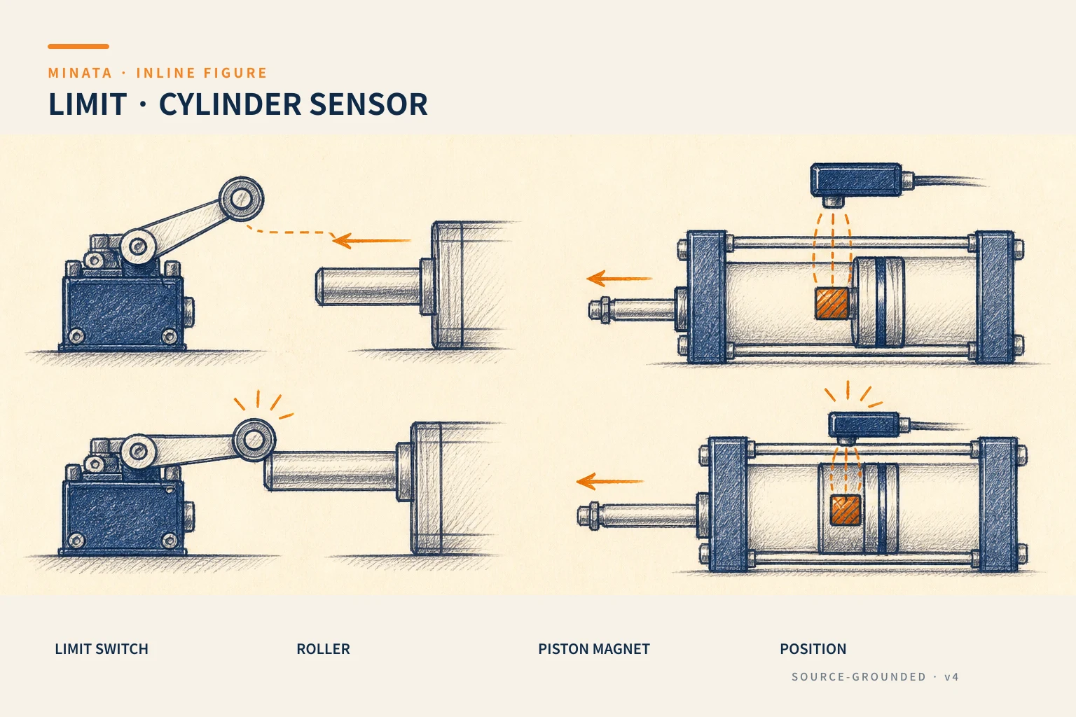
An important electrical note: the limit switch's contact carries a limited current. Do not run a large current (a contactor coil, a power load) straight through it — let it control an interposing relay (#11), and let the relay switch the load. This extends the contact's life and keeps the position signal clean.

The door safety switch: an important variant
A special family of limit switch is the guard-door/gate safety switch. When a machine guard door is opened, this switch breaks the circuit to stop the dangerous motion. Its mandatory features:
- Positive opening: like the E-stop (#09), the contact is mechanically forced open when the door opens, not relying on a spring.
- Interlock and defeat-resistant types: some use a key/code so the operator cannot easily "trick" the switch by wedging an object in.
- NC wired into a hardware safety circuit, not just into the PLC — true to the fail-safe spirit.
This is where the limit switch touches machine safety; do not use an ordinary limit switch for personnel protection.
The cylinder sensor: picking up the magnet on the piston
In a pneumatic cylinder, the piston usually carries a magnet ring. The cylinder body has a groove for mounting a magnetic sensor; when the piston (carrying the magnet) reaches the sensor's position, its field triggers the sensor to report "the piston is here". This tells you the cylinder has fully extended or fully retracted without any external mechanical part.
There are two main families:
- Reed switch: two metal reeds in a glass tube that pull together in a magnetic field. Cheap, simple, low consumption. Downside: being a mechanical contact, it has a finite life, can weld shut when switching an inductive load, and is sensitive to strong external fields.
- Electronic sensor (hall/magneto-resistive): no mechanical contact, far more durable, fast switching, good vibration resistance, usually with a PNP/NPN output and an indicator LED. A little dearer than reed but worth it for a high-frequency mechanism.
For a cylinder switching millions of cycles, the electronic sensor is almost always the right choice; reed suits sparse, simple, low-cost applications.
Why each cylinder usually needs two sensors
A cylinder has two meaningful positions: fully extended and fully retracted. Fitting two sensors — one at each end — lets the PLC know exactly where the mechanism is, instead of guessing by time:
- Confirm before the next step: the PLC only allows the next step when it sees the "fully extended" signal (exactly the lesson at the top — wait for confirmation, not for seconds).
- Detect a jam: if a extend command is given but the "fully extended" signal never appears within the allotted time, the PLC knows the mechanism is jammed and reports a fault instead of running blind.
- Detect drift/slip: if the signal suddenly disappears while "fully extended", the air pressure may have dropped or the mechanism drifted.
This is how a "mute" cylinder becomes a "speaking" mechanism, letting the sequence run safely and self-diagnose. The cost of one extra sensor is tiny against the value of a machine that knows where it is.
Bringing the signal to the PLC
- Choose NPN/PNP to match the PLC input (as in #10, #16, #17); for a 2-wire reed, check leakage/voltage-drop compatibility.
- The sensor's indicator LED helps set the position: slide the sensor along the groove until the LED lights exactly when the piston is at end of travel, then tighten it down.
- Use the signal as both a step condition and a diagnostic condition: combine it with a timer to catch a jam (commanded but not arrived within the allowed time).
- Name the I/O clearly: for example
CYL1_ext, CYL1_ret — this speeds up reading the program and fault-finding (related to #32 on the I/O list).
Filtering the signal: contact bounce and mechanical vibration
Both the limit switch and the reed sensor are mechanical contacts, so they exhibit bounce on open/close: a burst of very fast 0-1-0 pulses over a few milliseconds (covered in #10). For an ordinary position signal, the PLC scans the program every few milliseconds so it is usually fine; but when you use the signal to count or to catch a precise edge, bounce can turn one actuation into several.
The remedy: add a debounce timer in the program — only accept the new state once it is stable for a short interval — or use an electronic (hall) sensor, which has no mechanical contact and barely bounces. Beyond that, machine vibration can make the mechanism oscillate around the actuation point, making the sensor flicker; fix it by exploiting the sensor's hysteresis, tightening the bracket, and placing the actuation point away from the vibration boundary.

Layout and protection on the machine
The mounting position governs the sensor's/switch's life and reliability:
- Avoid direct impact: position the limit switch so the object presses gradually through the roller/lever, not slamming straight into the body — a hard impact cracks or misaligns it. For a long, high-inertia travel, use a damped lever.
- Avoid direct spray of chips, water, oil: shield it or choose a high IP class; metal chips clinging to a magnetic sensor can cause false readings.
- Route wiring tidily and secured: a moving mechanism drags its cable; use a cable chain and leave a bend radius so the wire does not break from constant flexing (related to #37 on cable ducts/bend radius).
- Easy to align and replace: place the sensor where a hand can reach and the indicator LED is visible — maintenance is far faster when a re-adjustment is needed.
A correctly chosen sensor mounted where chips bury it or the cable flexes to breaking will still stop the machine; the mounting matters as much as the device choice.
A reference engineering scenario
The illustration below is a reference approach in the spirit of MINATA's design thinking; the final ratings and configuration must be confirmed against the actual documentation, standards and equipment.
On a MINATA clamp-cut cell, the clamping cylinder has two electronic sensors reporting "clamp fully open" and "clamp fully closed" to a Delta AX-308E. The ST program only allows the blade down when it sees the "clamp fully closed" signal — exactly what was missing in the incident at the top. If the clamp is commanded but the fully-closed signal still does not appear after the set time, the PLC stops the cycle and lights a "clamp not closed" fault instead of bringing the blade down blind.
The mechanical end positions of a large sliding table use roller limit switches, wired NC into the limit circuit so that overrunning the travel cuts out safely. This "cylinder sensor for the sequence + limit switch for the hard limit" pairing is a pattern repeated across many cells.
Common mistakes
- Running the next step on a timer instead of waiting for a real position-confirmation signal.
- Running a large current straight through a limit-switch contact.
- Using an ordinary limit switch for a door-safety function (no positive opening).
- Choosing reed for a high-frequency cylinder → early wear/welding.
- Fitting one sensor, no signal at the other end → a jam cannot be detected.
- Mis-wiring NPN/PNP; setting the sensor position carelessly and not tightening it, so it drifts with vibration.
Mechanism-position checklist
- [ ] Every important step waits for a position-confirmation signal, not for seconds.
- [ ] The limit-switch lever/roller style matches the direction the object arrives from.
- [ ] Safety/limit signals wired NC; door safety uses a positive-opening type.
- [ ] No large current through a limit-switch contact (use a relay).
- [ ] High-frequency cylinder: use an electronic sensor instead of reed.
- [ ] Each cylinder has signals at both ends to detect jam/drift.
- [ ] NPN/PNP matches the PLC; align the sensor by its LED, then tighten it.
The limit switch and the cylinder sensor are how a machine "senses" its own mechanisms. A sequence is only safe when each step is confirmed by real position — without them, every command is just a hope that the mechanism arrived where it should.
Read more automation knowledge at MINATA: https://minatavn.com/en/blog/industrial-automation
Previous — #17: Proximity sensors: inductive and capacitive: https://minatavn.com/en/blog/automation-17-proximity-sensors
Next — #19: Solenoid valves and pneumatic cylinders: controlling pneumatic motion: https://minatavn.com/en/blog/automation-19-solenoid-valves-pneumatic-cylinders
View all MINATA technical articles