Learn Automation with MINATA #19: Solenoid Valves and Pneumatic Cylinders — Controlling Pneumatic Motion
Solenoid Valves and Pneumatic Cylinders: Controlling Pneumatic Motion
A cylinder pushing a workpiece runs too fast and slams into the stop with a bang every cycle. The operator complains the machine is noisy and the workpiece edges are dented. The technician plans to fit a smaller cylinder — but the problem is that there is no flow-control valve setting the speed, and where there is one it is fitted the wrong way (metering the inlet instead of the exhaust). Simply fitting two exhaust-metering flow controls correctly and re-tuning makes the cylinder run smoothly while keeping full force.
Compressed air is the most common and cheapest way to make linear motion in an automatic machine: clamping, pushing, lifting, stopping. The core pair is the solenoid valve — playing the role of an "air-direction switch" controlled by the PLC — and the pneumatic cylinder — the mechanism that turns air pressure into pushing force. Understanding these two, plus how to set the speed, is mastering most of the simple motion on a machine.
This article explains single- and double-acting cylinders, 5/2 and 5/3 solenoid valves, setting the speed with exhaust metering, wiring the valve coil to the PLC safely, and the common pneumatic faults.
This article states control principles. Detailed pneumatic design (flow, cylinder sizing, pressure safety) must follow calculation and the applicable standards; always relieve the pressure before any mechanical work.

The pneumatic cylinder: single- and double-acting
A cylinder turns air pressure into piston force. Two main types:
- Single-acting: air pushes the piston one way only, the other way relying on a return spring (or gravity). It saves air and wiring, but the return force is weak and the stroke is limited. Suited to simple actions like a light push or a spring-return clamp.
- Double-acting: air pushes the piston both ways through two ports. Strong force and control in both directions — the most common type for clamping, pushing, lifting a load.
A cylinder's push force depends on pressure × piston area; the retract side of a double-acting cylinder has a smaller area (the rod takes up space), so the retract force is less than the extend force. This is worth remembering when designing which direction bears the load.

The solenoid valve: an air-direction switch
The solenoid valve decides which port of the cylinder the air enters. Valves are denoted by "number of ports / number of positions":
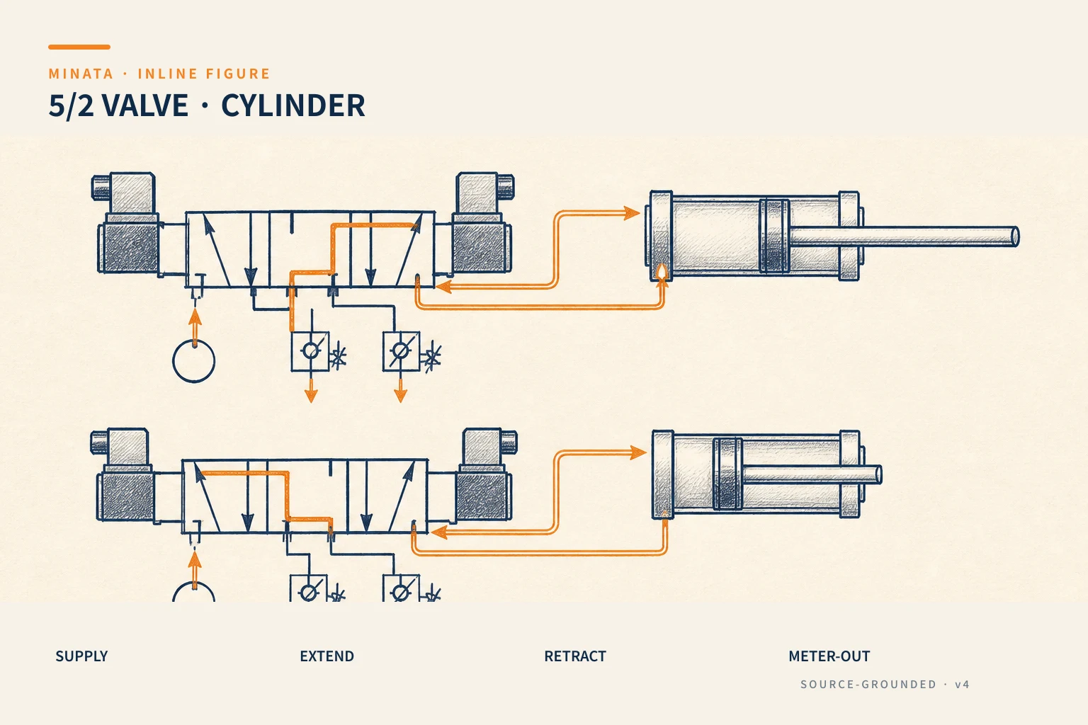
- 5/2 valve: 5 ports (1 supply, 2 to the cylinder, 2 exhaust), 2 positions. This is the standard valve for a double-acting cylinder: one position sends air into the extend chamber (piston extends, retract chamber exhausts), the other position reverses it.
- 3/2 valve: 3 ports, 2 positions — used for a single-acting cylinder (one air line, on/off).
- 5/3 valve: like the 5/2 but with a mid position — allowing the piston to stop mid-stroke (closed-centre type) or to exhaust both chambers (open-centre type, a "soft" piston). Used when a mid-stop or free release is needed.
There are also two ways to hold the valve position:
- Single solenoid + return spring: energise and the valve shifts, de-energise and the spring returns it to a default position. Safe on power loss because the cylinder goes to a predetermined position — so choose the default as the safe position.
- Double solenoid: each coil pushes the valve one way; the valve holds its position on power loss (a latching type). Handy when you want the cylinder to hold state during a power cut, but you must weigh whether that is safe.
Setting the speed: exhaust metering (meter-out)
This is the secret to making a cylinder run smoothly — and the mistake in the opening example. To set the speed, fit a throttle-check valve at the cylinder port. There are two ways:
- Meter-in: throttling the air flow into the cylinder. The piston tends to run jerkily, especially with a changing load, because the incoming air compresses unstably.
- Meter-out: throttling the air flow out of the opposite chamber. The exhausting chamber creates a "back-cushion", keeping the piston running smoothly and steadily even when the load changes. This is the standard method for most applications.
So on a double-acting cylinder, fit two throttle-check valves at the two ports, configured meter-out, and tune them so each direction runs fast enough without slamming. The check valve ensures only the exhaust direction is throttled, while the supply direction stays free-flowing.
Indispensable pneumatic accessories
A good air circuit also needs:
- Filter–regulator–lubricator (FRL): filters dust/water from the air, sets a stable working pressure, and (in some systems) adds lubricating oil. Dirty/wet air is the number-one cause of valves and cylinders failing early.
- Quick-exhaust valve: raises the speed when the piston needs to move fast in one direction.
- End-of-stroke cushion: many cylinders have an air cushion at the end to reduce impact — combined with meter-out for smoothness.
- Safety/dump valve (soft-start / dump valve): relieves pressure safely on stop or maintenance — always relieve the pressure before any mechanical work on a pneumatic mechanism.
Roughly sizing force and cylinder
You do not need a complex formula to choose a reasonable cylinder size, just the root relationship: push force ≈ pressure × piston area. From there:
- The larger the piston diameter, the stronger the force at the same pressure. A Ø32 cylinder gives several times the force of a Ø16 at the same 6 bar.
- Working pressure is usually around 5–6 bar; do not design right at the mains' maximum, since the pressure can drop when many devices share it.
- Leave a force margin (~30–50%): friction, a changing load and worn seals all "eat" some of the real force. Choose a slightly oversized cylinder so you do not have to raise the pressure to compensate later.
- Retract force is less than extend force: for a double-acting cylinder, the rod takes up space in the retract chamber, so the area is smaller — if the retract direction is the one bearing the load, size it by this smaller area.
Beyond force, mind that the stroke is long enough for the action, and the side load/moment — a pneumatic cylinder does not take side load well and needs guidance (a slide rail, a guided cylinder) when the load is off-centre.
Maintenance and common pneumatic faults
Pneumatics is simple but has a few classic "ailments"; knowing them in advance speeds up diagnosis:
- Air leaks: a hiss at a fitting, a cracked tube, a worn seal. A leak both wastes compressor power and drops the pressure, making the cylinder weak/slow. Check fittings and replace cracking tubes periodically.
- Water in the air: compressed air carries moisture that condenses into water in the lines and cylinder, causing rust and sticking valves. This is why the filter–water separator (FRL) is mandatory, and the receiver should be drained periodically.
- Sticking/slow-shifting valve: from dirt, lack of lubrication (in systems that need it) or a weak coil. A slow-shifting valve throws the sequence off-beat.
- Cylinder weakening over time: a worn piston seal lets air pass between the two chambers — force drops, motion becomes sluggish. This is natural wear; replace the seal set or the cylinder.
- Jerky running after a while: usually from a mis-set flow control or dirty air — recheck the meter-out and the filter.
A good habit: when a cylinder "runs oddly" (slow, weak, jerky), check the pressure and cleanliness of the air first, then suspect the device — most pneumatic faults come from dirty/wet air and pressure leaks, not a broken mechanism.

Wiring the valve coil to the PLC
The solenoid valve coil is an inductive load like a relay coil (#11), so:
- The PLC output should switch the valve coil through an interposing relay, or directly if within rating, and always with a suppression element (diode/RC) to protect the semiconductor output.
- Many valves mount on a manifold with built-in indicators and protection, wired to a common connector — compact and easy to maintain.
- Combine it with the cylinder sensor (#18): the PLC commands the valve, then waits for the sensor to confirm the piston has arrived, before moving on — not running by time.
A reference engineering scenario
The illustration below is a reference approach in the spirit of MINATA's design thinking; the final ratings and configuration must be confirmed against the actual documentation, standards and equipment.
On a MINATA clamp-push cell, the double-acting clamp cylinder is controlled by a single-solenoid 5/2 valve + return spring, with the default (power-loss) position chosen as clamp released, safe. Two exhaust-metering flow controls are tuned so the clamp opens/closes smoothly, without slamming. A Delta AX-308E output switches the valve coil through a relay with a suppression diode.
The ST sequence: command the clamp valve open → wait for the "clamp fully closed" sensor (#18) → only then allow the cut step. If the signal does not appear within the time, the PLC reports a "low air / clamp jam" fault and stops cleanly. Thanks to meter-out + waiting for confirmation, the cell is both smooth and safe — exactly what was missing in the "slam" incident at the top.
Common mistakes
- No flow-control valve, or fitting meter-in → the cylinder is jerky/slams at end of travel.
- Choosing a double-solenoid 5/2 where you actually need "power loss → safe position".
- Dropping the filter–regulator (FRL) → dirty/wet air fails the valve and cylinder early.
- Forgetting coil suppression → the PLC output is damaged.
- Running the next step on a timer instead of waiting for the sensor to confirm position.
- Doing mechanical work on a pneumatic mechanism without relieving the pressure → dangerous.
Basic pneumatics checklist
- [ ] Choose the cylinder (single/double) and size the force by pressure × area, remembering the retract force is less.
- [ ] The right valve: 3/2 for single, 5/2 for double, 5/3 when a mid-stop is needed.
- [ ] Choose single/double solenoid by the power-loss safety requirement.
- [ ] Fit two exhaust-metering (meter-out) flow controls for smooth running.
- [ ] Have an FRL (filter–regulator), consider a safety dump valve.
- [ ] Valve coil suppressed; switch through a relay if it exceeds the output rating.
- [ ] The next step waits for the sensor to confirm position, not for seconds.
- [ ] Always relieve pressure before mechanical maintenance; drain the receiver periodically.
The solenoid valve and the pneumatic cylinder are the simplest yet most capable motion pair on a machine. What separates a "noisy, jerky" pneumatic cell from a "smooth, precise, safe" one is usually not a more expensive device — it is choosing the right valve, setting the exhaust metering correctly, keeping the air clean, and always waiting for real position confirmation.
Read more automation knowledge at MINATA: https://minatavn.com/en/blog/industrial-automation
Previous — #18: Limit switches and pneumatic-cylinder sensors: https://minatavn.com/en/blog/automation-18-limit-switches-cylinder-sensors
Next — #20: Motors, brakes and clutches in machine drives: https://minatavn.com/en/blog/automation-20-motors-brakes-clutches
View all MINATA technical articles