Learn Automation with MINATA #20: Motors, Brakes and Clutches in Machine Drives
Motors, Brakes and Clutches in Machine Drives
A Z axis raises the working head via a motor through a gearbox. Mid-travel, the power fails. With no brake, gravity pulls the head into free fall, slamming into the workpiece below — the fixture is wrecked and it nearly caught the hand of someone standing near. An expensive lesson: on a vertical axis or a suspended load, a motor losing power loses its holding ability, and what must save that situation is a brake that clamps itself when the power is lost.
The drive is where control meets mechanics: the motor makes torque, the gearbox trades speed for force, the brake holds or stops, the clutch engages/disengages the drive. This article focuses on the foundational "devices" of the drive — especially the spring-applied, electrically-released electromagnetic brake, a safety detail beginners often overlook. Speed control and precise positioning (VFDs, servos, encoders) are covered in a later series; here we lay the foundation.
This article surveys the common motor types, the gearbox's role, the principle and use of the fail-safe electromagnetic brake, the clutch and the clutch-brake unit, and control from the PLC.
This article states principles. Choosing the motor, brake and safety factor for a suspended load must follow calculation and the applicable standards; a load lifting people/a dangerous load has stricter safety requirements of its own.

Motors: the common types
A quick survey to orient (details in the VFD/servo series later):
- Three-phase induction motor: simple, durable, cheap, the most common for pumps, fans, conveyors. Runs at a near-fixed speed on the mains; to change the speed, use a VFD.
- Gear motor: a motor with an integral reduction gearbox — giving low speed, high torque compactly, very common for conveyors and slow-rotating mechanisms.
- Servo and stepper: for precise positioning and speed control, with feedback (servo) — for an axis that needs the exact position/speed. Covered in detail in Stage 7.
In this foundational article, just remember: choose the motor by the load's torque – speed – duty, and precise speed control needs a VFD/servo — a bigger motor is not the answer.
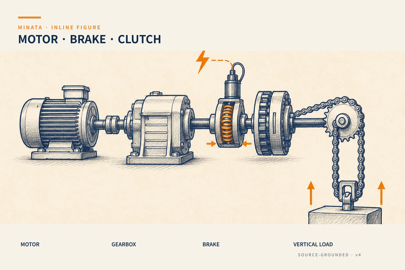

The gearbox: trading speed for torque
A gearbox reduces the speed and raises the torque accordingly (ignoring losses). It lets you use a high-speed, low-torque motor (cheap, compact) to drive a slow, heavy load. A few practical points:
- The gear ratio is chosen for the load speed needed and the torque required.
- The gearbox type (in-line, right-angle, planetary…) is chosen for the mechanical layout and precision.
- Self-locking: some gearboxes (worm gear) tend to self-lock, but self-locking must not be treated as a safety brake for a suspended load — a separate brake is still required.
The electromagnetic brake: why it must be "spring-applied, electrically released"
This is the most important part of the article. The electromagnetic brake used in machines has two opposite philosophies:
- "Power-on to brake" type: energise to clamp. It sounds reasonable but is dangerous: power loss means brake loss, and a suspended load falls. Very rarely used for safety holding.
- "Spring-applied, electrically released" type: a spring always clamps the brake; when energised, the coil overcomes the spring and releases the brake so the shaft can turn. When power is lost (or E-stop, or a fault), the spring clamps by itself and holds the shaft.
The second type is precisely fail-safe — the same spirit as the NC/E-stop in #09, #10: a fault brings the system to the safe state by itself. This is the type mandatory for a vertical axis, a suspended load, a load that could fall. It solves exactly the Z-axis incident at the top: on power loss the spring clamps and the working head stays put instead of falling.
A few notes on using a brake:
- Release/clamp sequence relative to the motor: on start, release the brake before or as the motor develops torque (avoid trying to turn against the brake). On stop, let the motor hold enough torque before clamping the brake, to avoid the load slipping in the hand-over moment — this is a subtle coordination point the PLC/VFD must handle.
- Holding brake vs dynamic stopping brake: a holding brake holds a shaft already stopped; to quickly stop a large inertia you need a brake able to dissipate energy or braking via the VFD (Stage 7 article).
- Brake-pad wear: the pad wears over time, the gap grows, and it needs periodic checking/adjustment; some have a wear-signal.
The clutch and the clutch-brake unit
A clutch engages/disengages the torque transmission between two shafts without switching the motor off — useful when one motor runs continuously but only occasionally needs to drive the load, or a fast disengage is needed.
A clutch-brake unit combines a clutch and a brake to engage the drive and stop fast cyclically — classic on presses and feeders that need high-frequency start/stop while keeping the motor running steadily. The clutch engages to drive, and when a stop is needed the clutch releases and the brake clamps almost instantly.
Both the clutch and the electromagnetic brake have a coil (inductive load), so apply the principle of #11: they need suppression and are usually controlled at 24VDC through a relay/dedicated driver.
Choosing a brake for a suspended load: holding torque and safety factor
A brake holding a vertical axis must produce a clamping torque greater than the torque produced by the load at the shaft where the brake is fitted, with a safety factor:
- Refer the load torque to the brake shaft: the brake is usually fitted at the motor end (high-speed, low-torque shaft), while the heavy load is after the gearbox. You must refer the load's torque through the gear ratio to the shaft that has the brake, to compare — this is where a miscalculation makes a brake "adequate on paper" yet slipping in reality.
- Safety factor: choose a brake torque with a considerable surplus over the load (usually several times), because pad wear, oil/grease getting onto the friction face, or a dynamic (shock) load all reduce the real holding ability.
- Account for the dynamic load, not just the static one: on an E-stop while running, the brake must arrest the inertia of the moving mass, not just hold a static load. For a large inertia, consider combining electric braking (VFD) before the brake clamps.
- Brake mounting position: fitting at the motor end is convenient and cheap, but if a clutch/gearbox in between fails, the brake loses effect on the load. For a dangerous load, consider a brake mounted directly on the output shaft, or add a mechanical anti-fall device.
In short: do not choose a brake merely by "can it hold the load static"; you must calculate the referred torque, the safety factor and the arresting situation while running.
Brake checking and maintenance
The brake is a safety detail yet it wears silently, so it must be put on the maintenance schedule:
- Brake-pad gap: as the pad wears the gap grows, and at some point the coil no longer releases/clamps decisively. Check and adjust the gap per the manufacturer's guidance.
- A clean friction face, no oil: oil/grease getting onto the brake face sharply reduces the holding torque — a dangerous and unexpected cause of brake slip.
- Periodic function test: verify the brake actually holds the load in the power-off state (per safety procedure, with an anti-fall measure during the test), not merely trusting that it is still good.
- Abnormal sound/sight: a squeal, an insecure hold, the shaft "drifting" slightly on stop are all signs to check immediately.
Because the consequences of a failed brake on a suspended axis are so serious, this is an item that should not be skipped in preventive maintenance.

Control from the PLC
- The brake/clutch coil is an inductive load → switch it through an interposing relay with suppression, not straight from a semiconductor output if it exceeds the rating.
- Tie the brake to the safety circuit: on E-stop or power loss, the spring brake must clamp by itself — meaning the supply to the brake-release coil should pass through the safety circuit, so a safe cut-out means the brake holds at once.
- Sequence in the program: the PLC (or VFD) handles the correct order of release brake – run – stop – clamp brake, waiting for confirmation where needed.
- Monitoring: bring the status signal (released/clamped, if available) back to the PLC to detect a brake that does not release (the motor tries to turn against the brake, easily burning out) or a brake that does not clamp.
A reference engineering scenario
The illustration below is a reference approach in the spirit of MINATA's design thinking; the final ratings and configuration must be confirmed against the actual documentation, standards and equipment.
On a cell with a vertical lift axis, MINATA uses a gear motor with a spring-applied, electrically-released brake. The brake-release circuit is supplied through the safety circuit, so on E-stop or power loss the brake clamps by itself and holds the lift head — exactly what would have saved the load-fall situation at the top.
In the Delta AX-308E program, the lift sequence is written carefully: release-brake command → confirm the motor has torque → run; on stop: hold torque → clamp brake → only then remove torque. The brake coil is switched through a relay with a suppression diode. As a result the vertical axis both runs smoothly and stays safe on a fault — the brake is a genuine part of the safety design.
Common mistakes
- A vertical axis/suspended load with no brake, or using a "power-on to brake" type → power loss means a fall.
- Treating a self-locking worm gearbox as a safety brake for a suspended load.
- The wrong release/clamp sequence relative to the motor torque → load slip, or the motor turning against the brake.
- Forgetting suppression for the brake/clutch coil → the PLC output is damaged.
- The brake-release circuit not passing through the safety circuit → E-stop does not make the brake clamp.
- Skipping periodic brake-pad wear checks → the brake weakens silently.
Basic drive checklist
- [ ] Choose the motor by torque–speed–duty; precise speed control uses a VFD/servo.
- [ ] Vertical axis/suspended load: a spring-applied, electrically-released (fail-safe) brake is mandatory.
- [ ] Do not treat gearbox self-locking as a safety brake.
- [ ] The release/clamp sequence is coordinated correctly with the motor torque.
- [ ] Brake/clutch coil suppressed; switch through a relay if it exceeds the rating.
- [ ] The brake-release circuit passes through the safety circuit (E-stop/power loss = clamp).
- [ ] Check brake-pad wear periodically; monitor the status if available.
The motor makes the motion, but it is the brake that decides what happens when everything loses power. For any load that could fall, a correctly fitted spring-applied, electrically-released brake is the line between "safe power loss" and an accident.
Read more automation knowledge at MINATA: https://minatavn.com/en/blog/industrial-automation
Previous — #19: Solenoid valves and pneumatic cylinders: controlling pneumatic motion: https://minatavn.com/en/blog/automation-19-solenoid-valves-pneumatic-cylinders
Next — #21: The latching circuit: momentary pushbuttons and holding state: https://minatavn.com/en/blog/automation-21-latching-circuit
View all MINATA technical articles