Learn Automation with MINATA #21: The Latching Circuit — The Foundation of Every Control Circuit
The Latching Circuit: The Foundation of Every Control Circuit
A beginner wires a motor control circuit, connecting the Start button straight to the contactor coil. The machine runs — but only while a finger is held on the Start button. Let go and the motor stops. He puzzles over why, until someone points it out: the Start button is a momentary type, its signal only exists while pressed (covered in #09). To "press once and run until Stop", you need a circuit that holds that state — a latching circuit.
The latching circuit (self-holding, or seal-in) is the building block of nearly every control circuit. Motor starting, reversing, star-delta, interlocking — all are built on it. Understanding this circuit thoroughly is understanding how a fleeting command becomes a maintained state, and how it is cancelled safely.
This article explains the principle of the latching circuit, how to wire Start/Stop/the auxiliary contact, the stop-priority rule, the variants, the behaviour on power loss, how to read the circuit on a drawing, and how to write the equivalent in a PLC using set/reset. Most control circuits in later articles are extended variants of this one, so time spent mastering it here saves a great deal later.
This article states principles. The component details, currents and safety must follow the real equipment and the applicable standards.

The problem: a momentary pushbutton does not latch
As learned in #09, the Start button is usually momentary — active only while pressed. If you wire this button straight to coil K, the coil is only energised while pressed, and lost when released. To use a momentary button to "switch on and hold", the circuit must feed the coil even after the button is released. That is exactly what the latching circuit does.

The principle: an auxiliary contact of coil K itself
The secret lies in an auxiliary NO contact of coil K itself, wired in parallel with the Start button:
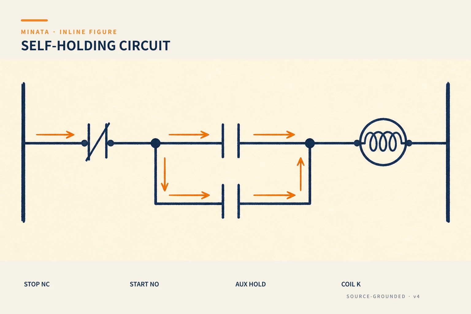
The sequence of operation:
- Press Start (NO) → current flows through Start, through the closed Stop (NC), to coil K → K is energised.
- Energising K closes the K auxiliary contact (NO). This contact is in parallel with Start, so now there is another path feeding the coil — Start is no longer needed.
- Release Start → Start opens, but current still flows through the K auxiliary contact → coil K stays held. This is the "self-hold".
- Press Stop (NC) → the circuit is broken → coil K loses power → the K auxiliary contact opens → the circuit returns to its initial state, ready for the next Start.
The subtle point: precisely because the holding contact belongs to coil K, when K loses power for any reason (Stop, power loss, a fault), the circuit releases itself — there is no "stuck" state.
Stop priority: Stop always beats Start
A basic safety requirement: if Start and Stop are actuated at the same time, Stop must win (the machine must not run). In the standard circuit above, Stop (NC) is wired in series on the path to the coil — when Stop is pressed, it breaks the circuit regardless of whether Start is being pressed. This is called a stop-priority circuit, and it is the correct wiring.
Conversely, if someone wires it wrongly so Start can "beat" Stop, a dangerous situation arises: hold Start and Stop has no effect. Always wire for stop priority.

Why Stop is wired NC (fail-safe)
Recalling the principle of #10: Stop is wired to a normally-closed (NC) contact. Normally Stop is closed so the circuit conducts; pressing Stop or a broken wire to Stop both open the circuit → stop. That is, a failure (broken wire, loose lug) brings the machine to the safe state by itself. Conversely, Start is wired NO: a broken Start wire at worst means "cannot start", which is not dangerous.
This is why in every latching circuit, Start is NO and Stop is NC — not an arbitrary convention but safety logic.
Common variants
The basic latching circuit has many variants depending on requirements:
- Adding more permissive conditions: wire more NC contacts of protections (thermal relay 95-96, #13), safety sensors, guard doors… in series on the path to the coil. Any condition opening stops the machine.
- Multiple Start / multiple Stop buttons: multiple Starts wired in parallel (starting from any of them); multiple Stops wired in series (pressing Stop anywhere stops it — correct for safety).
- Status indicator: another K auxiliary contact feeds a "running" lamp — but remember #09: the lamp should reflect the real state (for example from motor feedback) where possible.
- Reset after a fault: some circuits require a reset press to restart after a protection trips, preventing the machine from restarting by itself.
The latching circuit in a PLC: set/reset
Moving to a PLC, the latching circuit has two equivalent ways to write it:
- The "seal-in" style in ladder: drawn just like the electrical circuit — a branch with a Start contact in parallel with a contact of the output bit itself, in series with the Stop condition, to the output coil. Intuitive for anyone used to electrical circuits.
- The set/reset style: in Structured Text (ST) or ladder, use a set instruction when Start and the permissive condition are present, and reset when Stop or a lost safety condition. An example ST idea:
IF bStart AND bPermit THEN bRun := TRUE; END_IF;
IF NOT bStop OR NOT bSafe THEN bRun := FALSE; END_IF;
Mind the Stop signal logic: if Stop is wired NC, the PLC input is at level 1 when "not stopped", so the reset condition must be written in that sense (#10 warned about inverting an NC signal). And reset must have priority within the same scan to keep "Stop wins".
The set/reset style is usually easier to maintain for complex multi-condition logic, because it separates clearly "what turns it on" from "what turns it off"; the seal-in ladder style, meanwhile, is intuitive for those used to electrical circuits and easy to map one-to-one to the device diagram. Both give the same behaviour — choose by the team's habit and the circuit's complexity, as long as you keep stop priority and fail-safe.

Behaviour on power loss and recovery
An important characteristic of a device-based latching circuit: on power loss the coil releases, and the circuit does not restart by itself when power returns. Because the running state is held by current through the auxiliary contact, losing power loses that current; when power recovers, the coil is still released and Start must be pressed again to run. This is usually the desired behaviour — the machine does not restart on its own after an outage, avoiding danger to a person who was working when the power failed.
If for some reason the machine must restart automatically after power returns (for example a supply pump maintaining a level), it must be designed deliberately and its safety weighed carefully — never left to happen by accident. With a PLC, mind how the state bit is retained/initialised after a power loss (retentive or not), so the restart behaviour matches the design intent; this is a topic met again in the power-loss/restart article (Stage 5).
Reading a latching circuit on a drawing
When reading an electrical drawing, a latching circuit has very easy-to-spot signs:
- Find a coil (K, KM…) at the end of a rung (near the neutral bus N).
- Looking upstream, you will see a parallel branch of the Start button and a contact with the same name as that coil (for example coil K, so a K contact). A contact bearing the coil's name, in parallel with Start, is exactly the "self-hold" sign.
- On the path to the coil there are usually NC contacts in series: Stop, thermal relay, safety — these are the stop conditions.
The naming convention matters greatly: the contact and coil of the same device carry the same symbol, differing only in role (coil vs contact). Grasping this convention lets you trace a circuit quickly, and it is the basis for reading more complex control diagrams (#26 covers how to read a diagram left→right, top→bottom in detail).
A reference engineering scenario
The illustration below is a reference approach in the spirit of MINATA's design thinking; the final ratings and configuration must be confirmed against the actual documentation, standards and equipment.
On a MINATA cell, the conveyor motor uses the classic device-level latching circuit: Start NO, Stop NC, the contactor auxiliary contact self-holding, with the thermal relay NC contact and the safety circuit in series. When any protection trips, the contactor coil loses power and the conveyor stops.
In parallel, this logic is also reflected in the Delta AX-308E as a set/reset pair: bConveyorRun is set when the run command and the conditions are present, and reset on Stop/safety/overload. A contactor auxiliary contact reports back to the PLC to confirm the contactor actually closed — if commanded but no feedback is seen, the PLC reports a fault rather than trusting blindly (true to the spirit of #09). Both layers — device and PLC — keep one consistent logic.

Common mistakes
- Wiring Start straight to the coil, forgetting the self-hold branch → you have to hold Start the whole time.
- Wiring so Start can beat Stop → Stop has no effect while Start is held.
- Using Start NC or Stop NO → losing fail-safe, prone to false running or being unable to stop on a broken wire.
- Multiple Stops wired in parallel instead of in series → one Stop cannot cut the whole circuit.
- Writing a non-priority reset in the PLC → a scan where the machine still runs despite Stop.
- Forgetting to put protection contacts (thermal relay, safety) in series in the holding circuit.
Latching-circuit checklist
- [ ] Start (NO) in parallel with the coil's own NO auxiliary contact.
- [ ] Stop (NC) in series, wired for stop priority.
- [ ] Permissive/protection conditions (thermal relay, safety) in series.
- [ ] Multiple Starts in parallel; multiple Stops in series.
- [ ] In the PLC: reset has priority, handle the NC-signal inversion correctly.
- [ ] Real status feedback (auxiliary contact) where confirmation is needed.
- [ ] Consider a reset after a fault to prevent auto-restart.
- [ ] Check the power-loss behaviour: the machine does not restart by itself when power returns (unless deliberately designed to).
The latching circuit is small and simple, but it is the template repeated in almost every control circuit that follows. Master four things — self-holding by an auxiliary contact, stop priority, Stop NC fail-safe, and how to translate it into set/reset in a PLC — and you have the foundation to read and build the more complex circuits in the coming articles.
Read more automation knowledge at MINATA: https://minatavn.com/en/blog/industrial-automation
Previous — #20: Motors, brakes and clutches in machine drives: https://minatavn.com/en/blog/automation-20-motors-brakes-clutches
Next — #22: The interlock circuit: mutual locking to prevent conflict: https://minatavn.com/en/blog/automation-22-interlock-circuit
View all MINATA technical articles