Learn Automation with MINATA #22: The Interlock Circuit — Mutual Locking to Prevent Conflict
The Interlock Circuit: Mutual Locking to Prevent Conflict
A motor-reversing circuit uses two contactors: one for forward, one for reverse (swapping two of the three phases). The installer forgets the interlock. One day, through an operating error, both contactors close almost at the same time — two phases are shorted through the main contacts, the short-circuit current surges, the breaker trips, and had it been slower the contacts would have exploded. This whole accident is prevented by one small detail: the interlock circuit.
An interlock forces two (or more) mutually exclusive states never to occur at the same time. Two reversing contactors, the star and delta contactors, two supply sources — pairs where closing simultaneously is a fault — all need an interlock. This is the basic safety circuit that goes alongside the latching circuit (#21) in almost every machine with multiple modes.
This article explains the principle of the electrical interlock by cross-locking, why a mechanical interlock is also needed, the concept of transition delay, how it applies to reversing and star-delta circuits, and how to do interlocking in a PLC.
This article states principles. For a dangerous load and safety requirements, choosing the interlock measure (electrical, mechanical, safety circuit) must follow a risk assessment and the applicable standards.

The principle: cross-locking with NC contacts
The most common electrical interlock is the cross interlock: using an NC contact of one coil in series in the other coil's circuit.
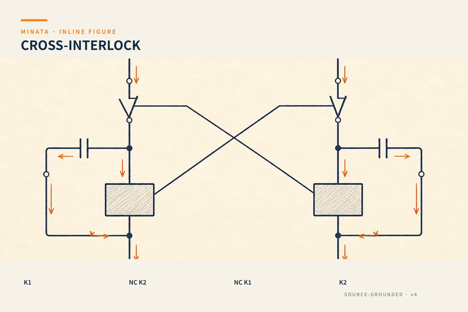
Consider two coils K1 and K2:
- The K1 coil circuit passes through an NC contact of K2.
- The K2 coil circuit passes through an NC contact of K1.
When K1 closes, the NC contact of K1 (in the K2 circuit) opens → even if Start2 is pressed, K2 cannot be energised. Likewise when K2 closes, K1 is locked out. Thus, at every moment only one of the two coils can close — the mutual-exclusion condition is guaranteed by the hardware itself, not dependent on the operator acting correctly.
Each coil still has its own latching circuit (#21) to maintain state after the button is released. The interlock only adds the condition "the other coil must be released" to each circuit.
Why use an NC contact and not NO for cross-locking? Because we want the condition "the other coil is off, then I may close". The other coil's NC contact is closed (conducting) when that coil is off, and opens as soon as that coil closes — exactly the logic needed. Mis-wiring it as NO gives the completely opposite result, losing the locking effect, so this is a spot to check carefully on the drawing and during wiring.

Why an electrical interlock alone is not enough
An electrical interlock with NC contacts is very good, but it has a weakness: if a contactor's main contact welds shut (welded by an arc, mechanically stuck), the electrical state may not reflect reality, and the electrical interlock can be bypassed. For a dangerous load (reversing a large motor), you also need:
- Mechanical interlock: a physical mechanism between the two contactors so that when one closes it mechanically blocks the other from closing. Many makers sell ready-made mechanical interlock kits fitting between two contactors of the same line.
- Interlock via positively-driven auxiliary contacts: use a contactor whose auxiliary contact is positively linked to the main contact, so the auxiliary state faithfully reflects the main state.
The practical principle: the electrical interlock is the first layer, the mechanical interlock is the backup layer for a welded-contact situation. The more dangerous the load, the more both are needed.
Transition delay: do not reverse instantly
When switching between two exclusive states (for example forward to reverse), do not reverse instantly. A contactor that has just released needs time for the arc to die completely and the contact to open decisively; if the other closes immediately, there can be a moment when both conduct. So:
- Add a time delay between "release this one" and "close that one" (usually with a timing relay, #25, or a timer in the PLC).
- For motor reversing, the pause also lets the motor slow down before reversing, avoiding too large a current and mechanical shock.
The interlock handles "not at the same time", while the delay handles "switch safely" — two things that complement each other.

Applications: reversing and star-delta
The interlock is the foundation for two classic circuits coming up:
- Forward-reverse reversing (#23): two phase-swapping contactors, mandatorily cross-locked (electrical + mechanical) so as not to short the phases. This is the most important interlock application.
- Star-delta starting (#24): the star contactor and the delta contactor must not close at the same time (causing a short circuit), so they are also cross-locked, with a timing relay for the star→delta transition.
Seen broadly: whenever there are two mechanisms/states where "both on is a failure", think immediately of an interlock.
Sequence interlock: enforcing the right order
Beyond the "mutually exclusive" kind (not at the same time), the interlock also has a sequence interlock kind: a mechanism is only allowed to operate when another mechanism is already in the right state. A few field examples:
- A pump runs only when there is priming water / the valve is open: put the "valve open" contact into the pump's run-permissive condition, avoiding the pump running dry.
- The spindle turns only when the guard is closed: the guard-door safety switch contact (#18) in series in the permissive circuit — the door open means it cannot run.
- The blade lowers only when the clamp is fully closed: as in the example in #18, use the "clamp closed" sensor signal as a condition.
In essence, this is still "an interlock condition contact in series in the permissive circuit" — but instead of cross-locking two coils to each other, it locks one coil to the state of another device/condition. A great many dangerous operating errors are blocked simply by adding the right one interlock condition to the permissive circuit.
Interlock with safety and external equipment
An interlock is not confined to one panel. It often connects to the safety circuit and external equipment:
- With the safety circuit: the safety conditions (E-stop, guard doors, safety mats) are brought in as "hard interlocks" — any unmet condition cuts the run permission, in hardware before reaching the PLC (the spirit of #09, #10).
- Between machines/stations: in a line, a downstream station can send an "I'm not ready" signal to lock the upstream station's feeding — an interlock between devices to prevent jams or collisions.
- With power/air/water: locking so the machine does not run when an auxiliary condition is missing (low air pressure, phase loss — using a monitoring relay, #11).
When designing, list clearly every interlock condition for each mechanism (what must be right for me to be permitted to operate) and represent them consistently in both the electrical diagram and the PLC logic. This list is also the basis for building the I/O table and the safety matrix later.

Interlock in a PLC
When controlling with a PLC, the interlock must still be kept, even at two layers:
- In the program: the condition to close output K1 must include "K2 is off", and vice versa. Write it clearly in the set/reset logic.
- Keep the interlock in hardware too: for a dangerous load, do not rely on software alone — still keep the electrical interlock via NC contacts between the two coils and/or a mechanical interlock. The reason: a software bug, a stuck bit, or a PLC fault must not be allowed to cause simultaneous closing.
This is a classic example of the principle "safety does not live entirely in the PLC" — like the E-stop (#09) that must cut out in hardware.
A reference engineering scenario
The illustration below is a reference approach in the spirit of MINATA's design thinking; the final ratings and configuration must be confirmed against the actual documentation, standards and equipment.
On a MINATA conveyor cell that must run in both directions, the two reversing contactors are cross-locked with NC contacts and fitted with a mechanical interlock kit. In the Delta AX-308E, the logic also only permits switching on one direction when the other is off, and inserts a time delay so the belt stops completely before reversing.
Thanks to three layers — electrical interlock, mechanical interlock and the software condition — even if the operator presses buttons chaotically or a signal fault occurs, the two contactors never close at the same time. This is exactly what was missing in the phase-short incident at the top.

Common mistakes
- Forgetting the interlock for two mutually exclusive contactors → phase short, short circuit.
- Using only a software interlock for a dangerous load, dropping the hardware interlock.
- No mechanical interlock, relying entirely on the electrical contact (welded-contact risk).
- Reversing instantly, with no delay → closing the other before the arc has died.
- Mis-wiring the interlock contact (using NO instead of NC) → losing the locking effect.
- Switching state while forgetting the sequence conditions (pump running dry, the blade lowering before the clamp closes).
Interlock checklist
- [ ] Two exclusive states: cross-lock with NC contacts between the two coils.
- [ ] Dangerous load: add a mechanical interlock and/or positively-driven contacts.
- [ ] Have a delay when switching state (do not reverse instantly).
- [ ] In the PLC: the exclusion condition in the logic, and keep the hardware interlock too.
- [ ] Check the correct NC/NO of the interlock contact.
- [ ] For motor reversing: enough slow-down time before reversing.
- [ ] List clearly every interlock condition for each mechanism, represented consistently in the electrical diagram and the PLC logic.
The interlock is one of the "cheapest yet most valuable" safety circuits: a few NC contacts prevent short circuits, explosions and equipment damage. Whenever two things are "both on is a failure", lock them together — electrically, and for a dangerous load mechanically too. And whenever a mechanism "may only run when the other condition is right", wire that condition into its permissive circuit. That is the whole spirit of the interlock: lock out what is not permitted, and permit what meets the conditions.
Read more automation knowledge at MINATA: https://minatavn.com/en/blog/industrial-automation
Previous — #21: The latching circuit: the foundation of every control circuit: https://minatavn.com/en/blog/automation-21-latching-circuit
Next — #23: Forward-reverse reversing of a three-phase motor: https://minatavn.com/en/blog/automation-23-motor-reversing
View all MINATA technical articles