Learn Automation with MINATA #23: Forward-Reverse Reversing of a Three-Phase Motor
Forward-Reverse Reversing of a Three-Phase Motor
A conveyor needs to run in both directions. The installer knows "swap two phases and the motor turns the other way", so wires two contactors, one connecting the phases straight, one swapping two phases. The machine runs both ways — until the first time someone presses the direction change a little too fast, the two contactors close overlapping for an instant, two phases short through the contacts, and the breaker trips with a bang. The reversing circuit lacks an interlock, and that is a fault that must not be allowed to exist.
Forward-reverse reversing is an application that directly combines three things just learned: phase swapping to change the direction of rotation (the idea from three-phase power, #04), a latching circuit for each direction (#21), and an interlock so the two directions never close at the same time (#22). Mastering this circuit is knowing how to assemble separate pieces of knowledge into a complete, safe circuit.
This article explains why swapping phases reverses the direction, the two-contactor power-circuit structure, the latching + interlock control circuit, the reversing delay, the shared protection, and how to do it in a PLC.
This article states principles. For a large motor and a high-inertia load, reversing must follow the manufacturer's guidance and the applicable standards; reversing while spinning fast causes a large current and shock torque.

Why swapping two phases reverses the motor
A three-phase induction motor turns with the rotating magnetic field created by the phase sequence. Change the phase sequence and the field's direction of rotation reverses, taking the rotor with it the other way. In practice, swapping just two of the three phases (for example L1 and L3) is enough to reverse — you do not need to change all three.
This is the basis of the reversing circuit: one contactor connects the phases in straight sequence (forward), one contactor connects them with two phases swapped (reverse). Choosing a direction means closing the corresponding contactor.
A practical note: "forward" and "reverse" are relative conventions — which one is "forward" depends on the machine. When installing new or replacing a motor, run a test at low speed/no load to confirm the direction is as intended before applying the load; if it turns the wrong way, just swap the two phases back at the connection point. For pumps and fans, turning the right way is especially important, because turning the wrong way can give poor flow while still looking "running" from outside.
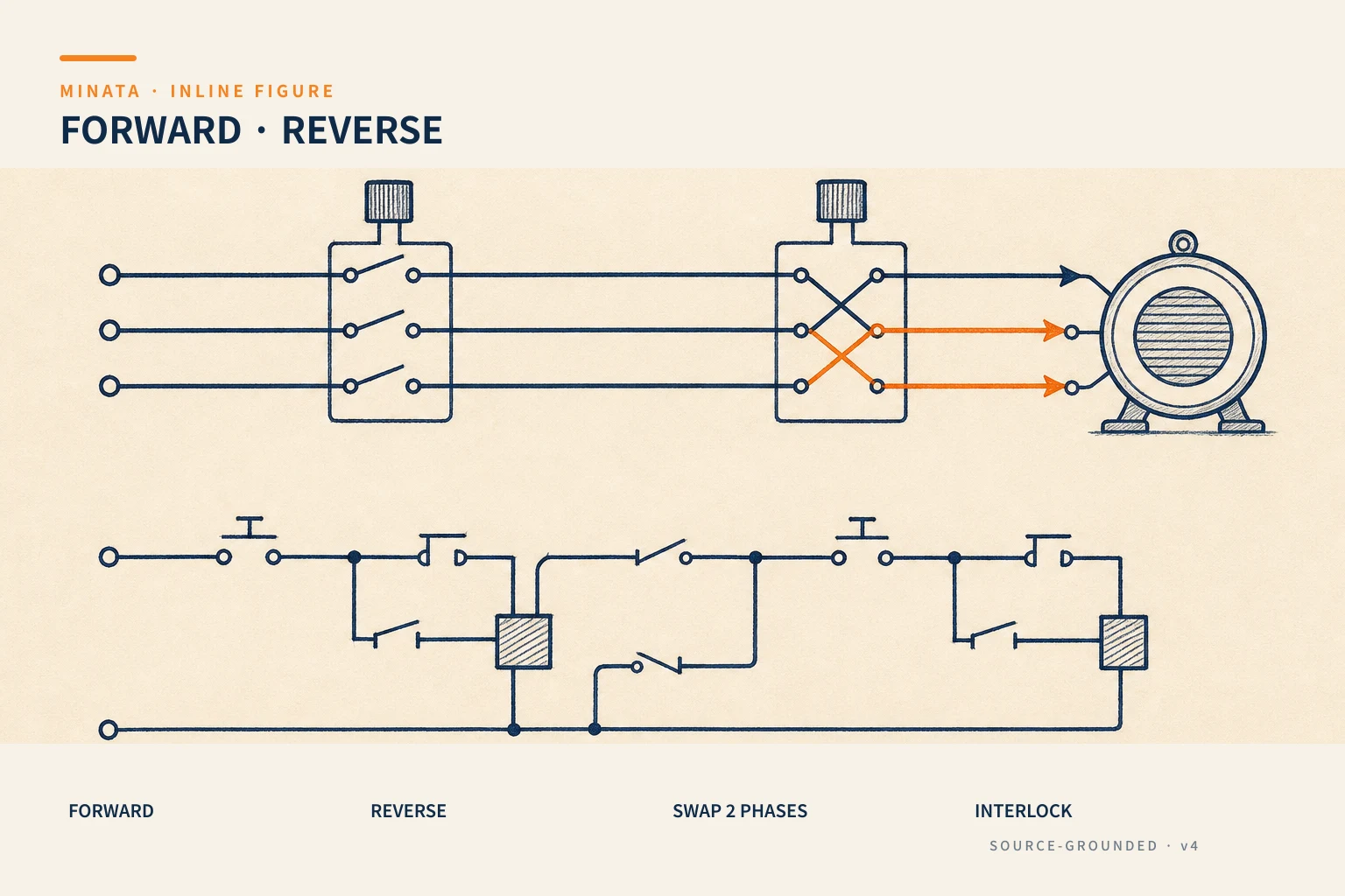

The power circuit: two contactors, one motor
On the power side:
- Forward contactor (KM-F): connects L1→U, L2→V, L3→W (straight sequence).
- Reverse contactor (KM-R): connects L1→W, L2→V, L3→U (L1 and L3 swapped).
- Both feed the same motor; only one may be closed at a time.
- A thermal relay (#13) is placed on the common path to the motor to protect against overload in both directions.
- A breaker/fuse (#14) protects against short circuit upstream.
The deadly point: if both contactors close at the same time, the main contacts connect L1 directly to L3 → a phase short circuit. This is why the interlock is mandatory, not optional.
The control circuit: latching + interlock
The control circuit combines two latching circuits (one per direction) and cross-locks them:
- Each direction has its own Start button (Start-F, Start-R) and a latching circuit using the auxiliary contact of that direction's contactor (#21).
- A shared Stop button (NC) in series stops both directions — multiple Stops are wired in series.
- Cross-locking (#22): the KM-F coil circuit passes through an NC contact of KM-R, and the KM-R coil circuit passes through an NC contact of KM-F. When one direction is closed, the other is locked out and cannot close even if Start is pressed.
- A mechanical interlock between the two contactors as a backup for the welded-contact case — for motor reversing this is almost standard.
Thanks to this, to change direction the operator must Stop first (release the running direction), then Start the other — or the circuit is designed to allow switching but with a safety delay (below).

The reversing delay: do not reverse while spinning fast
Reversing a motor spinning fast is very harsh: the field reverses while the rotor still turns the old way, producing a very large current (like plugging) and shock torque that harms the mechanics, belts and couplings. So:
- Insert a time delay between releasing one direction and closing the other (a timing relay, #25, or a PLC timer), enough for the arc to die and the motor to slow down.
- For a high-inertia load, consider letting the motor come nearly to a stop before reversing; or use a VFD with soft-reverse capability (Stage 7) when frequent reversing is needed.
The interlock handles "not at the same time", the delay handles "reverse smoothly" — as noted in #22, two things that complement each other.
Ways to brake and stop a motor
Reversing is closely related to how you stop, because "reversing while spinning" is itself a harsh kind of braking. A few ways to stop a three-phase motor, to set the right context:
- Coast to stop: cut the power and let the motor spin on inertia until it stops on its own. Simple, no shock, but slow — not suitable when you need a fast stop or to hold position.
- Plugging: swapping phases while spinning to create reverse torque, stopping very fast. But the current and shock are very large, harming the motor and mechanics; use only when truly needed and with calculation, usually with a speed-control relay to cut out near stop, avoiding the motor turning backwards.
- Braking with a mechanical brake: a spring-applied, electrically-released electromagnetic brake (#20) to hold/stop, especially a vertical axis.
- Dynamic braking / VFD braking: the VFD controls a smooth deceleration and dissipates the energy through a braking resistor (Stage 7) — the modern way for a fast yet smooth stop.
In a device-based reversing circuit, the safest way is still Stop → wait to slow down (delay) → reverse, avoiding turning every direction change into an uncontrolled plug-brake.
Choosing devices for a reversing circuit
A few notes when choosing devices for a reversing set:
- Contactors rated AC-3 (or AC-4 if much reversing/jogging): frequent reversing is a heavy duty; for continuous jog/reverse consider AC-4 or derating (#12).
- A dedicated reversing contactor pair: many makers sell a contactor pair with a power link bar and a standard mechanical interlock kit — using this is tidier and less error-prone than assembling your own.
- One thermal relay, placed after the point where the two directions merge, to protect the motor in both directions with the same FLA setting.
- Pushbuttons: usually Start-F (green), Start-R (green/different label), Stop (red); a dual button with direction-arrow labels can be used. Follow the colour code of #09.
Choosing the right dedicated device set from the start makes the reversing circuit both standards-correct and easy to maintain, rather than a patchwork that easily forgets the interlock.

In a PLC
When controlling with a PLC:
- Two output bits (run forward, run reverse) with set/reset latching logic, and an exclusion condition in software ("only switch on forward when reverse is off" and vice versa).
- Insert a timer for the reversing delay.
- Still keep the hardware interlock (NC contacts + mechanical) — do not entrust all safety to software, true to the principle of #22.
- Bring the two contactors' auxiliary contacts back to the PLC to confirm the real state and detect a welded contact.
A reference engineering scenario
The illustration below is a reference approach in the spirit of MINATA's design thinking; the final ratings and configuration must be confirmed against the actual documentation, standards and equipment.
On a MINATA two-way conveyor cell, the two reversing contactors are cross-locked with NC contacts and have a mechanical interlock kit. A shared thermal relay protects against overload in both directions. The Delta AX-308E keeps the exclusion logic in the program and inserts a time delay so the belt stops completely before reversing, avoiding a current shock.
The operator changes direction by pressing Stop then pressing the desired direction; if a reverse direction is pressed while running, the PLC ignores it until the current direction has released and the delay has elapsed. The three protection layers — electrical interlock, mechanical, and the software condition — ensure the two contactors never overlap, exactly what was missing in the phase-short incident at the top.

Common mistakes
- Building a reversing circuit but forgetting the interlock → a phase short when switching fast.
- Only an electrical interlock, missing the mechanical interlock for a dangerous load.
- Reversing instantly while the motor spins fast → a large current and mechanical shock.
- Placing the thermal relay for only one direction, leaving the other unprotected.
- In the PLC, relying entirely on software, dropping the hardware interlock.
- Multiple Stops wired in parallel instead of in series.
- Not test-running the direction of rotation before applying the load, letting a pump/fan turn the wrong way unnoticed.
Reversing-circuit checklist
- [ ] KM-R swaps exactly two phases; KM-F connects straight.
- [ ] Each direction has a latching circuit; a shared Stop (NC) in series, stop priority.
- [ ] Cross-lock with NC contacts + mechanical interlock.
- [ ] Have a reversing delay; for a heavy load, let it slow down before reversing.
- [ ] A shared thermal relay protects both directions.
- [ ] PLC: exclusion condition + timer, still keep the hardware interlock.
- [ ] Auxiliary-contact feedback to the PLC to detect a welded contact.
- [ ] Test-run at no load to confirm the correct direction of rotation before applying the load.
- [ ] Much reversing/jogging: choose contactors rated AC-4 or derate.
- [ ] Use a dedicated reversing contactor pair (with link bar and mechanical interlock) where possible, to reduce wiring errors.
The reversing circuit is the first test of whether you have truly mastered the latching circuit and the interlock — because it is those two assembled around a simple idea: swap two phases. Do it right and you have a tidy, safe direction-changing set; do it without the interlock and you leave a short-circuit trap waiting to be triggered. And once you understand the reversing circuit, the star-delta circuit in the next article is just adding one contactor and one timing relay to the very same latching + interlock principles.
Read more automation knowledge at MINATA: https://minatavn.com/en/blog/industrial-automation
Previous — #22: The interlock circuit: mutual locking to prevent conflict: https://minatavn.com/en/blog/automation-22-interlock-circuit
Next — #24: Star-delta starting: reducing motor starting current: https://minatavn.com/en/blog/automation-24-star-delta-starting
View all MINATA technical articles