Learn Automation with MINATA #25: Timing Relays — ON-Delay, OFF-Delay and Applications
Timing Relays: ON-Delay, OFF-Delay and Applications
A panel with a VFD runs hot. The panel cooling fan switches off at the same time as the machine, so right after the stop the heat stored in the VFD is not blown out and the components stay hot longer than necessary. Fixing this needs nothing expensive — just an OFF-delay timing relay so the fan runs on for a few minutes after the machine stops before it too switches off. A small device, one "delay" function, solving exactly the problem.
The timing relay brings the element of time into a control circuit: doing something after a delay, holding a state for a further interval, or generating a pulse/flash to a rhythm. It is the missing piece for building sequences with waiting steps — from star-delta (#24) and the reversing delay (#23) to countless "wait, then act" processes.
This article explains the two basic types, ON-delay and OFF-delay, through timing charts, the other types (pulse, flasher), practical applications, and how to translate them into TON/TOF/TP timers in a PLC.
This article states principles. The relay type, time range and accuracy must follow the real device and the application requirement.

Reading the timing chart
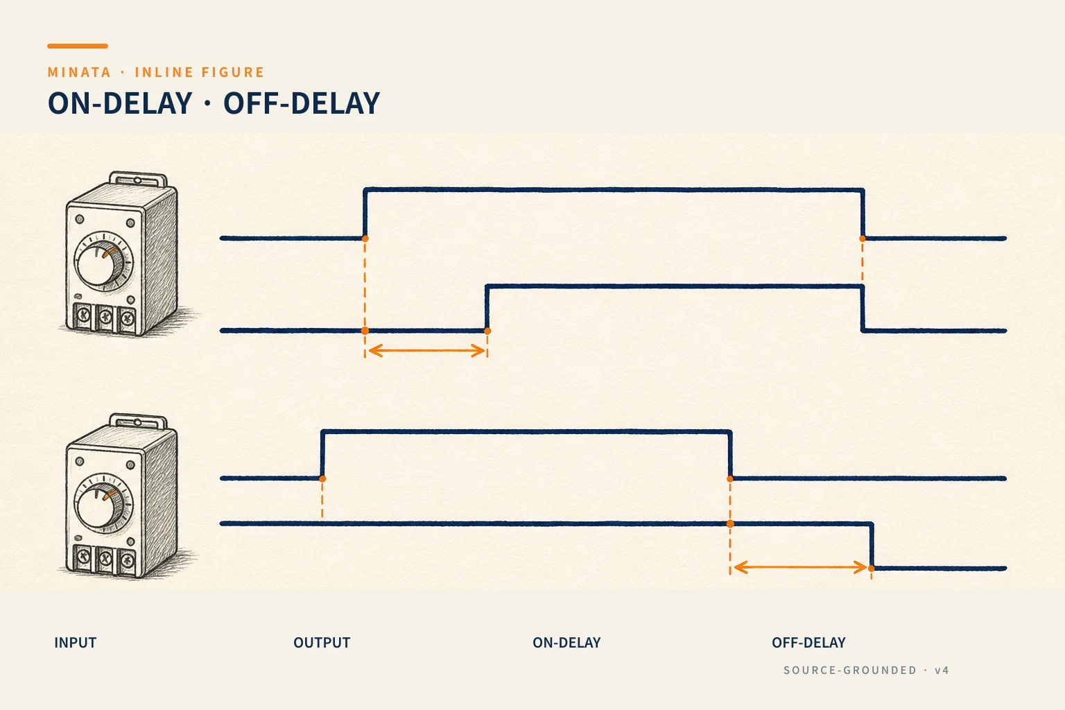
The fastest way to understand a timing relay is to look at the timing chart: the horizontal axis is time, and two lines show the input (the trigger condition) and the output (the relay contact). The difference between the types lies in how the output is "offset" from the input.

ON-delay
This is the most common type:
- Input turns on → the relay starts counting; after time T, the output turns on.
- Input turns off → the output turns off immediately, and the counter resets.
In other words: the output only turns on if the input is held long enough (≥ T). Applications:
- Waiting to stabilise: wait for pressure/temperature/speed to reach a threshold before allowing the next step.
- A sequence with waiting steps: start this device T seconds after another (starting in turn so the currents do not pile up).
- Filtering a fleeting signal: a signal is only taken as real if it lasts ≥ T — rejecting noise and contact bounce (#10, #18). If the signal flickers shorter than T, the output never turns on.
OFF-delay
The opposite of ON-delay:
- Input turns on → the output turns on immediately.
- Input turns off → the output is held for a further time T before turning off.
The classic application is the opening example:
- A cooling fan runs on after the machine/VFD stops, to purge the heat.
- Keeping lubrication/lights on for a while after stopping.
- Ignoring a short loss of signal: hold the output through input flickers shorter than T (for example an object passing a sensor with a small gap).
Other types: pulse and flasher
Beyond the two basic types, the timing relay has many variants:
- One-shot / pulse: the input turning on makes the output turn on for exactly an interval T then switch off by itself, regardless of whether the input is still held. Used to create a "beat" of fixed length.
- Flasher: the output turns on and off alternately to a cycle, for a blinking indicator lamp or to make a rhythm.
- Delay on both on and off, cyclic on-off, retriggerable: many function families for specialised sequences.
- A dedicated star-delta timing relay: integrates the release-Y / delay / close-Δ logic for #24.
Many multi-function timing relays let you choose the function and time range with rotary switches on the body, one device usable for many jobs.
The timing relay in a multi-step sequence
The real power of the timing relay shows when you chain several to make a sequential process. For example, a process starting three devices in turn a few seconds apart (so the starting currents do not pile up):
- Press Start → device 1 runs, and at the same time an ON-delay T1 begins counting.
- After T1 → device 2 runs, and an ON-delay T2 begins.
- After T2 → device 3 runs.
Each step "opens the way" for the next by a delay. This is how old lines created a sequence before the PLC — and understanding it lets you read the many pure-device control panels still out in the field.
However, when the sequence is complex (many steps, many branching conditions, error handling), chaining many physical timing relays becomes tangled and hard to modify. That is where the PLC wins: the same sequence written with timers + a state machine (learned in Stage 5) is far clearer and easier to maintain. Physical timing relays suit a few simple steps; a large sequence should move to a PLC.

Mechanical, pneumatic or electronic types
Timing relays come in several technologies, chosen by accuracy and environment:
- Electronic (most common): an electronic timing circuit, a wide range, accurate, with many adjustable functions on one body. The default choice for a modern panel.
- Mechanical/synchronous-motor: a mechanism rotating with time; durable, little affected by electrical noise, but bulky and less flexible. Still found on old equipment.
- Pneumatic timer: delay by air escaping through a throttle orifice (like the flow-control valve in #19); mounted with a contactor, needing no electronics, tolerant of harsh environments, but of moderate accuracy and drifting with temperature.
For most applications today, an electronic timing relay is good enough and economical. Choose another type only for a specific reason (a special environment, compatibility with old equipment, a no-electronics requirement).
Choosing and wiring a timing relay
- Time range: choose a range covering the value needed, setting it in the middle of the range for accuracy (like choosing a thermal relay, #13).
- Accuracy and repeatability: for a time-sensitive sequence, mind the tolerance; an electronic relay is more stable than a mechanical one.
- Supply voltage and trigger type: some need a separate supply, some are triggered by the control voltage itself; read the pin diagram carefully.
- Output contact: a suitable current/load type; for a large load switch through an interposing relay (#11).
In a PLC: TON, TOF, TP
When using a PLC, a physical timing relay is usually replaced by a standard IEC 61131-3 timer block (detailed in #48):
- TON = ON-delay: the output rises after the input has been held for the set time.
- TOF = OFF-delay: the output is held for the set time after the input turns off.
- TP = pulse: the output turns on for a fixed interval.
The advantages of a PLC timer: adjust the time in software, use as many timers as you like without any device cost, and easily monitor the value being counted. But the reading principle is exactly the same timing chart as above — grasp the chart and you understand both physical relays and PLC timers.
Using ON-delay to filter noise: a practical tip
One of the less-mentioned but very useful uses of ON-delay is filtering a flickering signal. Suppose a sensor reports "object present" but occasionally flickers noise for a few tens of milliseconds due to vibration or electrical noise. If the logic reacts instantly, it may miscount or transition wrongly.
Put a short ON-delay (for example a few tens to a few hundred milliseconds) on the signal: only when the signal is held stable long enough is it taken as real. Any noise pulse shorter than the set time is ignored. This is precisely the debounce mentioned in #10 and #18, implemented with time. In a PLC, just a small TON on the input signal suffices.
Conversely, OFF-delay helps stabilise a signal that often flickers off: if a signal is valid but occasionally drops for a moment (an object with a gap, a vibrating contact), OFF-delay holds the output through those short losses, giving a "smoother" state. Combining the two types in the right places is a simple yet powerful tool to clean up a signal before feeding it into the control logic.

A reference engineering scenario
The illustration below is a reference approach in the spirit of MINATA's design thinking; the final ratings and configuration must be confirmed against the actual documentation, standards and equipment.
On MINATA machine cells, the element of time is used in many places: TON to wait for enough air pressure before letting a mechanism run; TOF for the panel cooling fan to run on after a stop; TP to create a push pulse of fixed length. With the Delta AX-308E, all of this is done with timer blocks in CODESYS, the times adjustable on the HMI, needing no physical timing relay.
In the pure-device part (where there is no PLC yet), simple cells still use discrete timing relays — for example a dedicated star-delta relay for a pump. In whichever form, the reading and the "delay on / delay off / pulse" thinking is the same.
Common mistakes
- Confusing ON-delay with OFF-delay → the sequence is off-beat.
- Choosing a time range that does not cover the value needed, or setting it at the edge of the range.
- Using ON-delay to filter noise but setting T too short → noise still gets through; too long → slow reaction.
- Switching a large load directly through the timing relay contact instead of through an interposing relay.
- In a PLC forgetting that TOF still holds the output after the input turns off → the downstream logic misreads the state.
Timing-relay checklist
- [ ] Identify the right type: ON-delay, OFF-delay, pulse or flasher.
- [ ] A time range covering the value needed, set near the middle of the range.
- [ ] Choose an accuracy suited to a time-sensitive sequence.
- [ ] Check the supply/trigger type and the pin diagram.
- [ ] Switch a large load through an interposing relay.
- [ ] In a PLC: use TON/TOF/TP of the right type, understanding TOF's holding behaviour.
- [ ] Consider a short ON-delay to filter signal noise; move a complex sequence to a PLC.
- [ ] Chain several timing relays for a simple sequence; read and check with the timing chart to avoid being off-beat.
The timing relay is small but opens a whole class of sequence circuits: whenever you need to "wait, then act" or "hold for a while longer", it is the answer. Master the ON-delay/OFF-delay timing charts here and you have the tool to read and build almost any timed sequence later, both in devices and in a PLC.
Read more automation knowledge at MINATA: https://minatavn.com/en/blog/industrial-automation
Previous — #24: Star-delta starting: reducing motor starting current: https://minatavn.com/en/blog/automation-24-star-delta-starting
Next — #26: Reading a control diagram left to right: https://minatavn.com/en/blog/automation-26-reading-electrical-diagrams
View all MINATA technical articles