Learn Automation with MINATA #26: Reading a Control Diagram Left to Right
Reading a Control Diagram Left to Right
A new technician is assigned to troubleshoot a stopped machine's panel. He opens the drawing, sees a forest of lines, symbols and numbers, then… folds it back up and goes to trace each wire with a meter. Half a day passes. Meanwhile, someone who can read a diagram needs only a few minutes' look to trace which rung feeds which coil, and which condition is open. The electrical drawing is the panel's map — being able to read it is the skill that separates a methodical troubleshooter from someone groping blind.
The good news: control diagrams follow one consistent set of conventions. Once you grasp the power-rail layout, how to read each rung, how contact and coil are named, and how cross-references work, almost every control drawing reads the same way. Earlier articles (the latching circuit, interlock, reversing…) gave you the "vocabulary"; this article teaches you to "read the sentences".
This article covers the diagram structure (power rails, rungs), the left→right and top→bottom reading order, the naming and rest-state convention, cross-references, and how to use the diagram to troubleshoot systematically.
This article states common conventions. The specific symbols can differ by standard (IEC, JIS, NEMA) and by factory — always read the symbol legend that comes with the drawing.

The structure: power rails and rungs
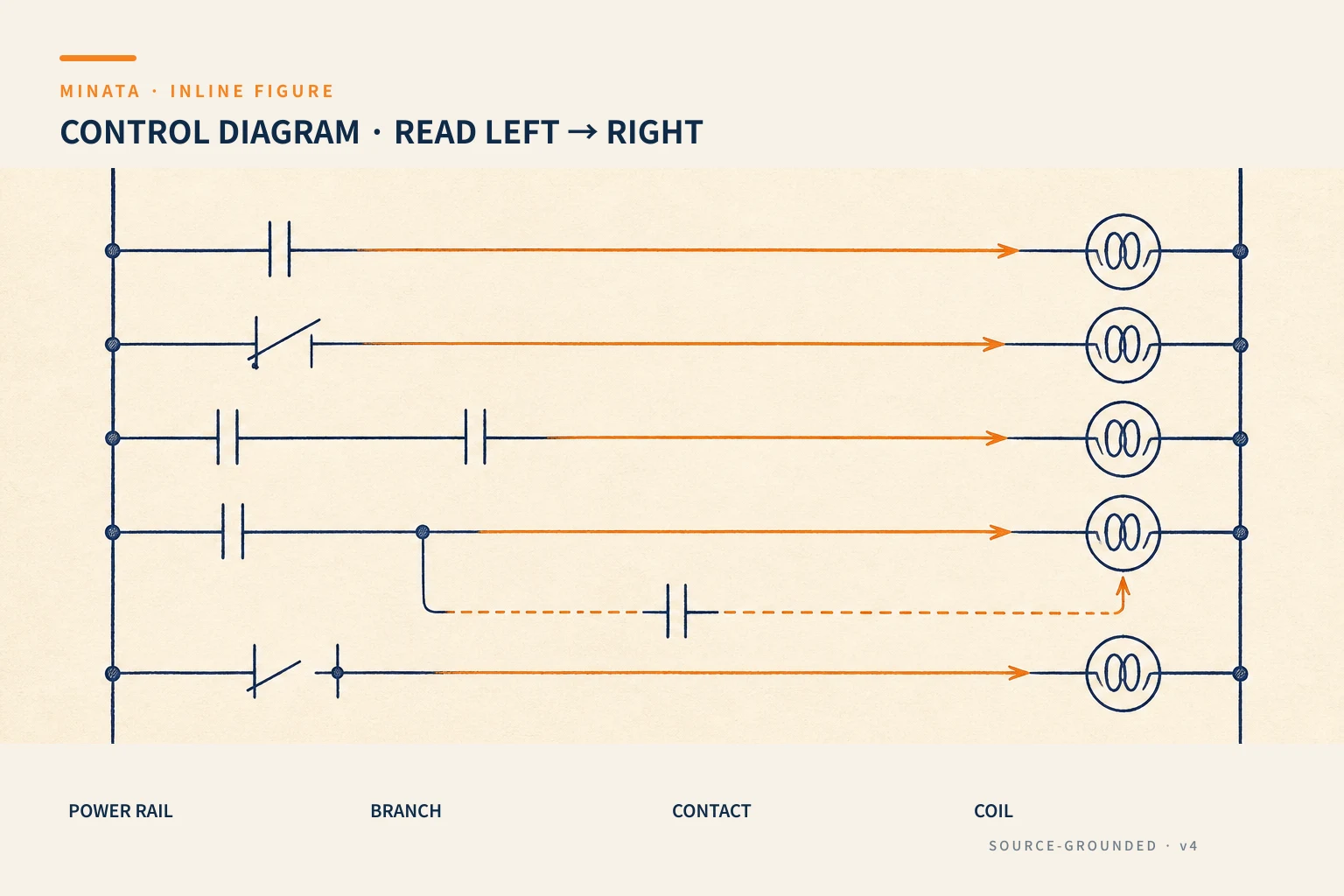
A ladder-style control diagram has a very regular layout:
- Two vertical rails = the power source: the left rail is one pole (for example L or +24V), the right rail is the other pole (N or 0V). Every rung draws power between these two rails.
- Each horizontal rung = one "line" of logic: read like a sentence, from the left rail to the right rail.
- Rung numbering: rungs are usually numbered (1, 2, 3…) in the margin for reference.

The reading rule: left → right, top → bottom
Two reading directions, do not confuse them:
- Within a rung, read LEFT → RIGHT: on the left are the conditions (contacts: buttons, sensors, relay contacts), on the right next to the N rail is the result (a relay/contactor coil, a lamp, a valve). Read it as a sentence: "if these conditions are met then energise that result".
- Between rungs, read TOP → BOTTOM: the rungs are arranged in order, usually reflecting the sequence or a functional grouping.
For example the rung "S1 // K1 — S0 — (K1)" reads as: "press Start S1 or the K1 self-hold contact is closed, and Stop S0 is not pressed → energise coil K1". This is exactly the latching circuit of #21, now read straight from the drawing.
The naming convention: contact matches coil
This is the key to tracing a circuit:
- The same symbol = the same device. Coil
K1 and every contact bearing the name K1 all belong to the same relay/contactor K1. When the coil is energised it changes the state of all contacts bearing that name at once, even if they are on different rungs. - Distinguish coil from contact: the coil is drawn as a circle (or a coil symbol) at the end of the rung; the contact is drawn as NO/NC (#10) in the condition part.
- Drawn in the REST state: as noted in #10, every contact is drawn in its de-energised, un-actuated state. When reading, ask "is this device at rest or actuated?" then deduce the contact state.
With this convention grasped, when you see a K1 contact on rung 3, you know immediately it is controlled by coil K1 on rung 1 — even if the two rungs are far apart on the drawing.
Cross-references: tracing coil and contact
On a large drawing, a coil can have many contacts scattered across many rungs, even many pages. The cross-reference solves this: next to a coil there is usually a list of the rungs containing its contacts, and next to each contact there is the rung number containing the coil.
For example, next to coil K1 it reads "3, 7, 12", meaning K1's contacts are on rungs 3, 7 and 12. So when troubleshooting, if you find a coil not pulling in, you can immediately trace everywhere its contacts affect, without scanning the whole drawing. This is the most time-saving tool when reading a complex diagram.

Symbols and legend: always read the legend
The symbols for contacts, coils and devices can differ between standards (IEC, Japan's JIS, America's NEMA) and between companies. A good drawing always has a symbol legend and a device list. Before reading in detail:
- Look at the legend to see how NO/NC, coils and special devices are drawn.
- Look at the device list to know what
K1, S0, F1… are (a contactor, a button, a fuse…). - Note the wire and terminal numbering convention (#28) to match the drawing to the real wiring in the panel.
Do not assume a symbol — one slash misread as turning NO into NC is enough to troubleshoot in the wrong direction, or worse to mis-wire when installing new. A few minutes reading the legend saves hours of mistaken tracing.
Power diagram and control diagram: two drawings, one system
A set of electrical drawings usually splits into two complementary parts; do not read them mixed together:
- Power (main) circuit: the part carrying the large current — from the breaker, contactor (main contacts) and thermal relay to the motor. The lines are usually drawn heavier, three-phase L1/L2/L3. This is where you read "how the power gets to the load" (#12, #13, #14, #23, #24).
- Control circuit: the small-current part — buttons, sensors, auxiliary contacts, contactor/relay coils. This is where you read "how the logic decides to switch on/off" (#21, #22, #25).
The join between the two drawings is the same-named device: coil KM is on the control diagram, while the main contacts of that same KM are on the power diagram switching the motor. When troubleshooting a motor that will not run, you must read both: check the control diagram for whether coil KM is energised, and the power diagram for whether the main contacts, thermal relay or wiring have a problem. Many difficult faults only reveal themselves when you cross-check the two drawings against each other.
Multi-page drawings and how to trace them
A large machine has multi-page drawings, and a circuit spreads across pages. How to keep from getting lost:
- Number the rungs continuously across the whole set (not resetting per page), so a cross-reference points to one unique rung whatever page it is on.
- Cross-references note both page/rung: for example "/5.3" means page 5, rung 3 — trace it and you arrive exactly.
- Read the contents/page map at the front of the set to know which page is the power source and which is each functional group.
- The terminal table and I/O table (#31, #32) are the bridge between the drawing and the real wiring in the panel — always cross-check the wire number on the drawing against the actual wire label.
With a well-conventioned drawing set, even one dozens of pages thick, you can still trace a signal end to end just by following the rung numbers and cross-references — this is why a consistent convention matters more than the drawing's prettiness.
Using the diagram to troubleshoot systematically
Being able to read the diagram turns troubleshooting from "groping" into "reasoning":
- Start from the symptom: for example "coil K2 does not pull in". Find the rung containing coil K2.
- Read that rung's conditions left to right: list every series contact that must be closed for K2 to be energised.
- Check each condition: which contact is open when it should be closed? Use the cross-reference to find which device controls that contact, then trace on.
- Narrow down to the root condition — it may be a tripped thermal relay (95-96 open, #13), an interlock, a sensor, or a broken wire.
This is far faster and surer than blindly measuring each wire, and it is why reading a diagram matters as much as wiring one.

A reference engineering scenario
The illustration below is a reference approach in the spirit of MINATA's design thinking; the final ratings and configuration must be confirmed against the actual documentation, standards and equipment.
When handing over and maintaining machine cells, MINATA keeps electrical drawings with clear rung numbering, cross-references and an I/O table. When a mechanism will not run, the technician opens the exact rung feeding the relevant coil, reads the condition chain, and traces via the cross-reference to the open condition — usually finding the cause (overload, interlock, sensor) in a few minutes.
For cells using the Delta AX-308E, besides the electrical diagram there is a PLC program; but the reading principle is similar: trace from the output (a mechanism not running) back to the conditions in the logic. A clear electrical drawing and a consistent I/O table (#32) are what let the receiving party read and understand fast — true to the spirit of a decent handover.
Common mistakes
- Reading contacts in their operating state instead of the rest state on the drawing.
- Skipping the legend, guessing symbols → misreading NO/NC.
- Not using the cross-reference, scanning the whole drawing to find a contact.
- Troubleshooting by blind measurement instead of reading the rung's condition chain.
- Confusing the two reading directions (within a rung left→right, between rungs top→bottom).
- Reading only the control diagram, forgetting to cross-check the power diagram when troubleshooting a motor.
Diagram-reading checklist
- [ ] Identify the power rails (left/right) and the rung numbering.
- [ ] Read each rung left→right: conditions on the left, result on the right.
- [ ] Remember a contact of the same name = the same device as the coil; drawn in the rest state.
- [ ] Use the cross-reference to trace coil ↔ contact.
- [ ] Read the legend and the device list before going into detail.
- [ ] Troubleshoot: from symptom → feeding rung → condition chain → the open condition.
- [ ] Read both the power and control diagrams; trace same-named devices between the two.
- [ ] Multi-page drawing: follow continuous rung numbers and page/rung cross-references.
- [ ] Cross-check the wire number on the drawing against the real wire label in the panel before concluding.
Reading an electrical diagram is a set of conventions learned in a few sessions, not an innate talent. Once you are used to the power rails, the reading direction, the naming convention and the cross-references, the drawing turns from a "forest of symbols" into a map that leads straight to the spot you need — and that is the foundational skill for all installation, handover and maintenance later.
Read more automation knowledge at MINATA: https://minatavn.com/en/blog/industrial-automation
Previous — #25: Timing relays: ON-delay, OFF-delay and applications: https://minatavn.com/en/blog/automation-25-timing-relays
Next — #27: Japanese-standard (JIS) electrical symbols on drawings: https://minatavn.com/en/blog/automation-27-japanese-electrical-symbols
View all MINATA technical articles