Learn Automation with MINATA #28: Wire and Device Numbering in a Control Panel
Wire and Device Numbering in a Control Panel
A well-running panel is handed over with no wire numbers and no device labels. Six months later the machine faults, and the maintainer (not the installer) opens the panel: a bundle of same-coloured, unlabelled, tangled wires. To find where one wire runs from and to, he has to pull it apart, trace with a meter, mark it temporarily — losing a whole session on what should be a few minutes. The same panel, numbered properly, would let the maintainer just look at the drawing, read the wire number, and go straight to the right terminal.
Numbering wires and devices is a task that costs little effort at installation but saves a great deal later. It turns a control panel from a "black box" into a searchable system, and it is the condition for the drawing (#26, #27) to have real meaning — because a drawing is only useful when it can be matched to the real wiring.
This article covers the device-tag rule, the wire-number rule, the "match in three places" principle, how to choose a numbering system, and the benefits for troubleshooting, handover and maintenance.
This article states common principles. The specific conventions (letters, number structure) may follow a standard (IEC 81346, JIS) or an internal company/customer rule — agreeing one system and using it consistently matters more than which system you pick.

The device tag
Each device in the panel is given a tag with a letter part (indicating the type) and a number part (distinguishing several of the same type):
- Q1 = the main breaker, KM1/KM2 = contactors, F1 = the thermal relay (or fuse depending on the system), K1 = an interposing relay.
- S1 = the Start button, S0 = the Stop button, B1 = a sensor, M1 = the motor, T1 = a timer, H1 = an indicator lamp.
The letter part follows a set convention (for example IEC 81346, or a JIS code like MC/THR from #27); the number part increments. This tag is written both on the real device (a label) and on the drawing, so that seeing one tells you the other. When the drawing says "KM1", there is exactly one device in the panel labelled KM1.
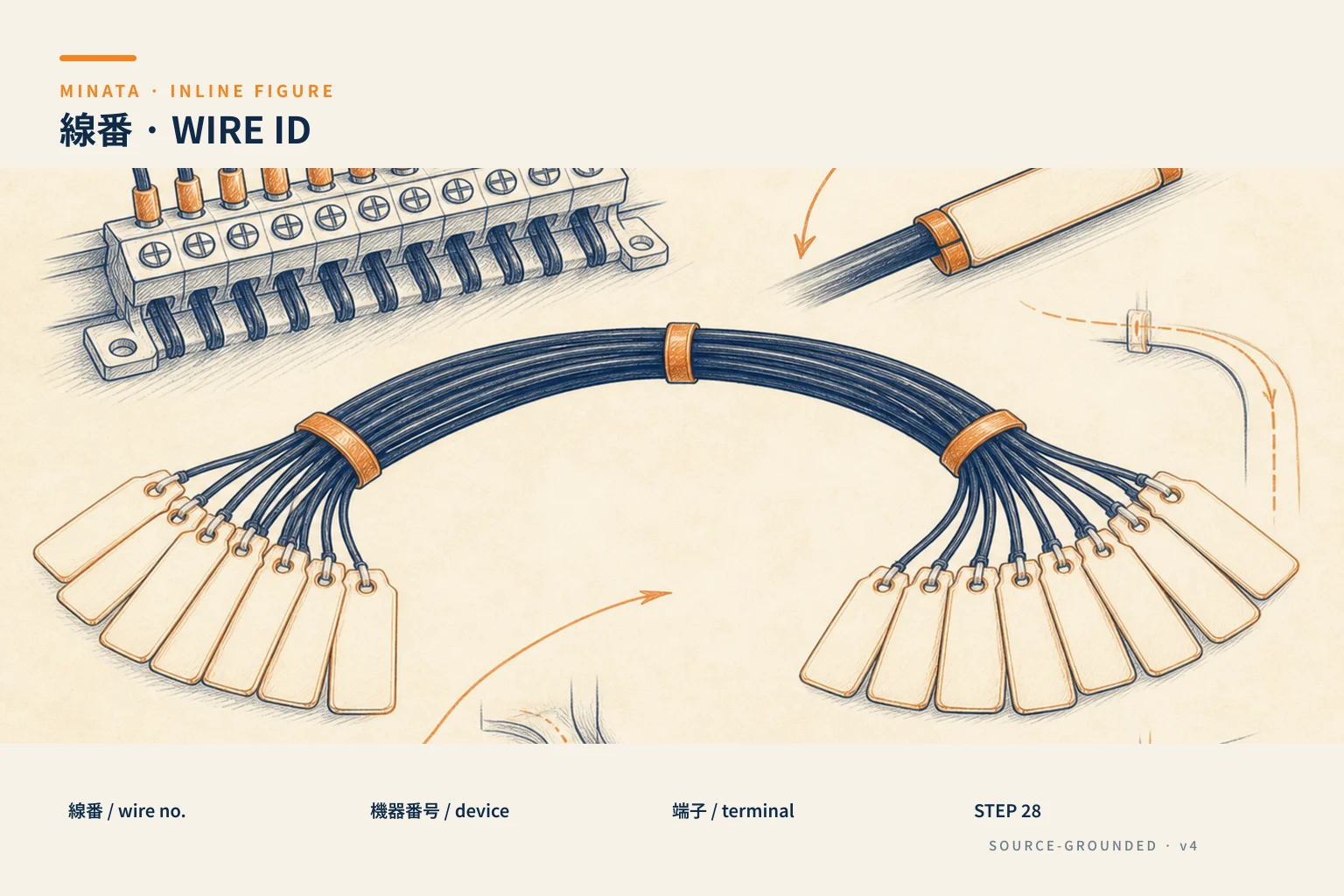

The wire number
Each segment of wire carries a wire number, printed on a ferrule at both ends of the wire:
- The same potential = the same number: all points connected together (not through a device) belong to one "electrical node" and carry the same wire number. When you see two wire ends with the same number W-104, you know they are the same wire/same potential.
- Through a device the number changes: before and after a contact/coil are two different potentials, so the wire numbers differ.
There are two common numbering schools: sequential (W-101, W-102…) or by circuit node/rung number (tying the wire number to the position on the drawing). The latter helps trace the drawing faster but is more complex to install. Choose one and keep it consistent across the whole panel.
The golden rule: match in three places
This is the most important point. A numbering system only has value when the labels match in all three places:
- On the drawing: the device tags and wire numbers printed on the diagram.
- On the real wire/device: the wire-number ferrule at both ends of each wire, the tag label on each device.
- At the terminal block: the number printed at each terminal position (#31), matching the wire number connected there.
When these three places match, the maintainer goes from a symptom on the drawing to the right real wire and the right terminal without tracing. Conversely, one place out of step (a replaced wire whose label was not changed, a drawing not updated) and the whole system loses trust — so updating the labels every time you repair is a mandatory discipline.
Ferrules, wire colour and supporting conventions
Beyond numbers, a few supporting conventions:
- Ferrules: slid onto the wire end, the number printed clearly, durable against oil/heat. Do not write on the wire with a marker — it fades quickly.
- Wire colour by function: many places have a colour convention (for example AC control wire, 24VDC wire, 0V wire, earth wire) per a standard/internal rule. Colour helps distinguish the circuit type quickly, complementing the wire number.
- Earth (PE): the protective wire has its own colour and symbol, not numbered like a signal wire.
- Durable device labels: printed/engraved, not paper stickers that peel in a workshop environment.
Colour and ferrules do not replace each other: the wire number tells "which wire", the colour tells "which circuit type" — use both.

Choosing a numbering system: simple or structured
There are several levels of "smart" numbering, chosen by the panel's scale:
- Simple sequential (W-101, W-102…): easy to install, enough for a small panel. Downside: the number alone does not tell you which circuit the wire belongs to; you have to consult the drawing.
- Structured/positional numbering: the wire number is tied to the rung or circuit node on the drawing (for example a wire on rung 12 carries a related number 12). The wire number lets you guess the position and trace the drawing very fast — but it demands careful planning and discipline when repairing.
- Hierarchical codes (per IEC 81346): for a large system, the device tag can have several layers — by function (=), location (+), product (-) — to identify across the whole plant, not just one panel. Powerful but heavy, needed only for large projects.
The practical principle: choose a level of complexity just enough for the scale and keep it consistent. A simple system used seriously beats a sophisticated one used half-heartedly. The worst thing is mixing several systems in the same panel.
Numbering for the PLC's I/O
When the panel has a PLC, numbering extends to the input/output signals:
- Each input/output has an address (for example %I0.0, %Q0.1 in CODESYS) and should be tied to a meaningful variable name (for example
B1_workpieceSensor, KM1_conveyorRun). - The signal wire number to the PLC matches that address/name, and matches the drawing.
- The link table "address ↔ variable name ↔ wire number ↔ terminal ↔ device" is precisely the I/O list (#32) — the most important document for reading and maintaining the PLC part.
Thanks to consistent numbering all the way to the I/O, when a sensor faults the maintainer goes straight from the HMI fault message (the variable name) to the terminal and the real wire. This is why numbering is not just "the electrician's job" but directly relates to PLC programming too — the two parts must share one name/number system.
Benefits: troubleshooting, handover, maintenance
- Fast troubleshooting: from a rung on the drawing (#26) straight to the real wire number and terminal, checking the right point instead of blindly measuring the whole bundle.
- Handover-ready: someone else — even one who did not do the installation — reads the drawing and the panel and understands, and can repair. This is the condition for a machine to "live" long-term, not depending on one person.
- Safe modification: when adding/removing a circuit, the numbering system tells you what is in use, avoiding mis-wiring.
- Building the I/O table and documentation: consistent numbering is the basis for the terminal table (#31) and the I/O list (#32).
Tidy wiring practice alongside numbering
Numbering goes hand in hand with tidy work to take effect:
- Route wires in ducts, cut to the right length: wires tidy in ducts (#37) are easier to trace by number than a tangle. Leave a modest spare length at the terminal for future repair.
- Group wires by circuit: wires of the same circuit/function run along the same route, separating power wires from signal wires to reduce noise (#36).
- Fit ferrules before connecting: slide the ferrule onto the wire before crimping the lug and connecting; fitting it afterwards is very hard.
- Cross-check while connecting: as you connect, tick it off on the drawing, so nothing is missed or double-connected — this is also part of checking the panel before energising (#39).
A fully-numbered panel with tangled wires is still hard to maintain; conversely, tidy wires with no labels are pretty but useless for troubleshooting. The two complement each other: tidy to see, numbered to look up.

A reference engineering scenario
The illustration below is a reference approach in the spirit of MINATA's design thinking; the final ratings and configuration must be confirmed against the actual documentation, standards and equipment.
In MINATA panels built for cells using the Delta AX-308E, every device has a tag (Q, KM, F, K, B, S…), every wire has a number ferrule at both ends, and the terminal block is numbered matching the drawing. So at handover, MINATA hands over a drawing set the receiver can read and trace at once; and for remote maintenance, the technician only needs to ask "is there voltage at terminal X1:4" to locate exactly.
This is part of the spirit of a decent handover: the machine is not just able to run at handover, but can be understood and repaired afterwards. A well-numbered panel speaks of professionalism more clearly than any advertising, and matters especially when working with Japanese customers, who value tidy handover documentation and long-term maintainability.
Common mistakes
- No numbering, or only partial numbering → troubleshooting becomes wire-groping.
- Labels not matching the three places (repairing a wire without updating the drawing/label).
- Writing the number on the wire with a marker → fading, unreadable after a while.
- Changing the numbering system midway, inconsistent within the same panel.
- Using colour instead of numbers (colour only tells the type, not which wire).
- Handing over without an updated drawing matching the real panel.
- Mixing several numbering systems in the same panel, leaving the next person unsure which convention to follow.
Numbering checklist
- [ ] Each device has a tag (letter for the type + number), written on the device and the drawing.
- [ ] Each wire has a number ferrule at both ends; the same potential = the same number.
- [ ] Labels match in three places: drawing ↔ real wire/device ↔ terminal.
- [ ] Use durable ferrules, do not write on the wire with a marker.
- [ ] Apply wire colour by function, complementing the number.
- [ ] Update the labels and drawing every time you modify.
- [ ] Hand over with a drawing matching the real panel.
- [ ] Fit ferrules before connecting; route wires tidily in ducts, separate power/signal.
- [ ] PLC: tie the wire number to the I/O address/variable name, build the I/O list (#32).
- [ ] Choose a numbering complexity just enough for the panel's scale; do not mix systems.
- [ ] Route wires tidily in ducts, separate power/signal, leave a spare length at the terminal.
Numbering wires and devices is the small discipline that makes the big difference between a panel that "runs" and one that is "maintainable". Spending a little effort at installation so everything matches in three places is a gift you give yourself — and anyone who opens the panel later.
Read more automation knowledge at MINATA: https://minatavn.com/en/blog/industrial-automation
Previous — #27: Japanese-standard (JIS) electrical symbols on drawings: https://minatavn.com/en/blog/automation-27-japanese-electrical-symbols
Next — #29: The power circuit diagram: reading and building the supply to the load: https://minatavn.com/en/blog/automation-29-power-circuit-diagram
View all MINATA technical articles