Learn Automation with MINATA #30: The Control Circuit Diagram — Reading and Building the Switching Logic
The Control Circuit Diagram: Reading and Building the Switching Logic
If the power circuit diagram (#29) is the "electrical pipeline" bringing energy to the load, the control circuit diagram is the "brain" deciding when to switch on and when to switch off. The same motor, the same contactor — but it is the control circuit that determines how it starts, how it stops, which protection cuts it, and what the operator sees on the indicator lamps. This is where every logic concept learned (latching, interlock, timing) meets.
The control circuit diagram (制御回路) is the part drawing the small-current circuit: pushbuttons, auxiliary contacts, protection contacts, relay/contactor coils, indicator lamps, timers. It is separate from the power circuit but tightly linked through the same-named device: a coil here controls the main contact over on the power side (#29).
This article builds a complete motor-starter control circuit — from the latching circuit to the run/fault lamps — explains how to read each rung, how it coordinates with the power diagram, and the common mistakes when designing a control circuit.
This article states principles. The safety details (E-stop, safety circuit) and specific devices must follow a risk assessment and the applicable standards.

The structure of a starter control circuit
Looking at the diagram, a motor-starter control circuit has a few rungs:
- Rung 1 — the latching circuit (#21): Stop (S0, a b/NC contact) in series, Start (S1, a/NO) in parallel with the KM1 self-hold auxiliary contact, then the overload-protection contact F1 (b/NC), to coil KM1.
- The run-lamp rung: a KM1 auxiliary contact (a/NO) feeds the green "running" lamp.
- The fault-lamp rung: the F1 contact (a/NO, 97-98) feeds the red "overload" lamp.
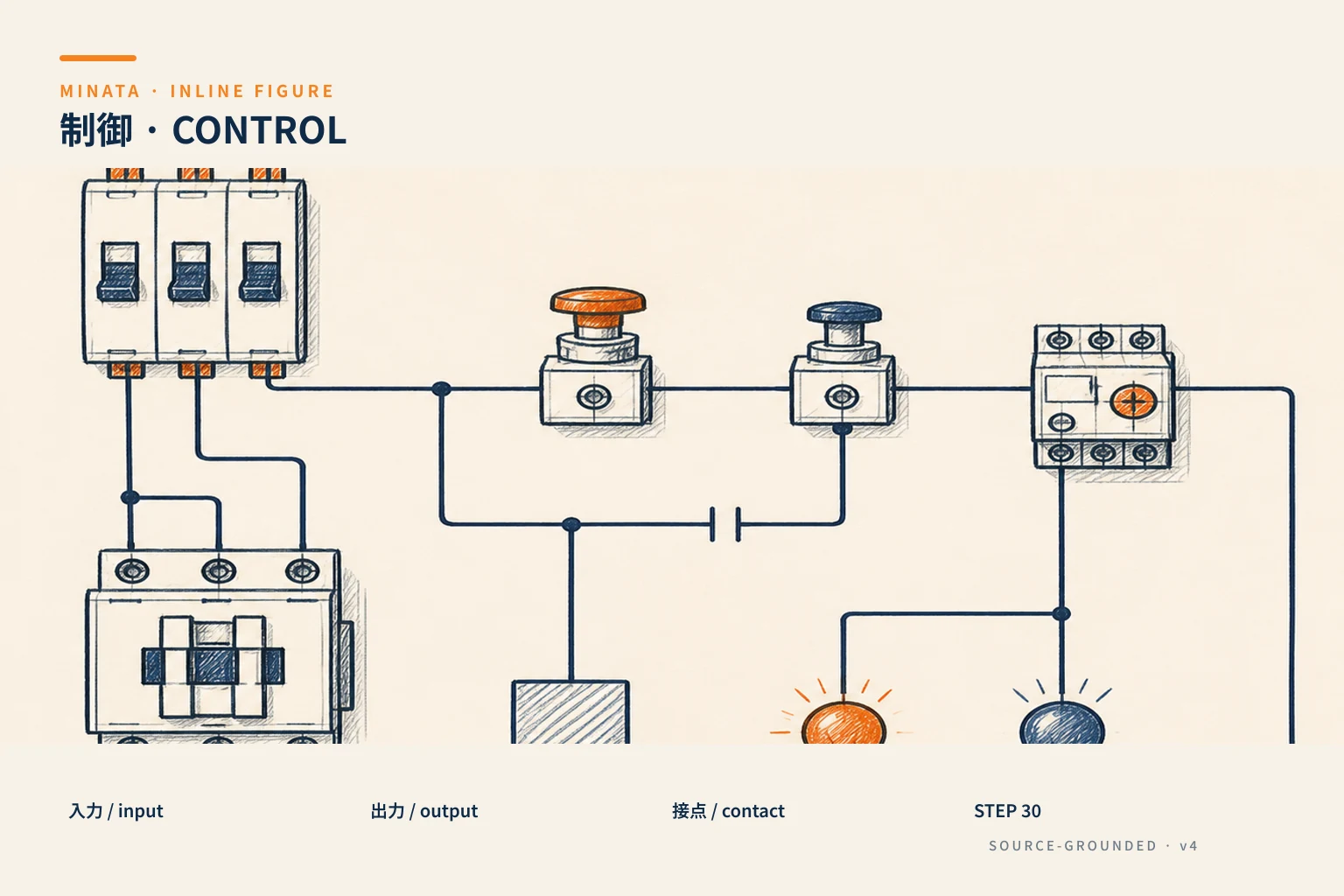
Read rung 1 as a sentence (using the JIS symbols of #27): "Stop not pressed (S0 closed), and (Start S1 pressed or KM1 self-holding), and the thermal relay not tripped (F1 closed) → energise coil KM1". This is exactly the motor-start circuit met many times, now drawn in full with the indicator lamps.

Reading the control circuit: rung by rung, left to right
Apply the rule of #26 exactly:
- Each rung read left → right: conditions (contacts) on the left, result (coil/lamp) on the right next to the N rail.
- Rungs read top → bottom: usually the top rung is the main logic (coil), the lower rungs are auxiliary (indicator lamps, signals).
- Same-named contact = same device: KM1 appears on rung 1 (coil), the self-hold rung (auxiliary contact), and the run-lamp rung (another auxiliary contact) — all belonging to the same contactor KM1.
Thanks to systematic reading, you see the logic at once: KM1 closes and the green lamp lights; F1 trips and cuts KM1 (the motor stops) and lights the red lamp. A complete status picture from just a few rungs.
Coordination with the power diagram
This is the important join (#29):
- The KM1 coil on the control circuit → controls the KM1 main contacts on the power circuit → switching the motor.
- The thermal relay F1 measures the current on the power circuit → the F1 contact (b on the coil rung, a on the fault-lamp rung) on the control circuit.
So when troubleshooting, always read the two drawings in parallel. For example the green lamp lights (KM1 is energised) but the motor does not run → suspect the main contacts or a phase on the power circuit (exactly the situation in #29). The two drawings complement each other to make the full picture.
Adding functions to the control circuit
The basic circuit is easily extended by adding conditions/rungs:
- E-stop and safety circuit: bring the NC contact of the E-stop and safety doors into the path to the coil — but safety must cut out in hardware, not only in this control circuit (#09).
- Interlock (#22): add the NC contact of the excluding coil into the other coil's circuit.
- Timer (#25): add a timing relay for a delay or a sequence.
- Mode selection: an Auto/Manual selector switch adds a condition rung for each mode.
- More indicator lamps/signals: report the state out to the HMI, PLC.
Every extension still follows the principle "add a condition contact to the right rung" — without breaking the foundational latch + protection structure.

The role of indicator lamps and status signals
In a control circuit, indicator lamps are not decoration but a channel of information for the operator (#09). A sensible lamp layout lets you understand where the machine is just by looking at the panel face:
- Green "running" lamp: from the contactor's auxiliary contact, or better from real feedback (the VFD is running, a motion sensor) — avoiding a "lying lamp".
- Red "fault/error" lamp: gathering the faults that stop the machine (overload F1, phase loss, safety) — the operator sees red and knows intervention is needed.
- Yellow "warning" lamp: anomalies that do not yet stop the machine but need attention.
Beyond lamps, the control circuit also outputs status signals to the PLC/HMI: an auxiliary contact reporting "closed", a fault signal for event logging. These signals turn a "mute" panel into a self-reporting system, helping operation and maintenance be proactive rather than guessing. Good lamp/signal design is part of a decent control circuit, not an add-on for looks.
The supply for the control circuit
The control circuit is usually supplied from 24VDC (through a power supply, #15) or 220VAC (through a control transformer/fuse), separate from the power circuit:
- 24VDC is common for a circuit with a modern PLC/sensors/HMI — safe, compact.
- 220VAC through a control transformer is common in a traditional device circuit with AC contactor coils.
- The control circuit has its own small fuse/breaker so one short does not pull down the whole panel.
Choose the control supply consistently across the whole panel, and note it clearly on the drawing (#28) so as not to fit the wrong coil voltage.
Drawing a readable control circuit: a few presentation rules
A logically-correct control circuit can still be hard to read if drawn carelessly. A few rules make the drawing readable and maintainable:
- Coils aligned on the right: place every coil/lamp next to the N rail (on the right), the conditions gathered on the left. Looking at the right column tells you how many "results" the drawing has.
- One coil per rung: each rung should have only one coil/lamp at the end, avoiding cramming several results into one rung and making it hard to read.
- Group by function: related rungs (one starter) placed near each other, with a title/note.
- Full cross-references (#26): next to each coil list the rungs containing its contacts; next to a contact note the rung containing the coil. This is what makes tracing fastest.
- Consistent rung and wire numbering (#28): so the drawing matches the real panel.
- Note the important conditions: a line of note (in Vietnamese, or Japanese for a Japanese customer) about the rung's intent helps the next person understand fast.
A good drawing is not just correct but tells the operating story to the reader — that is the standard MINATA aims for at handover.
From a device circuit to a PLC: the same logic
The heartening thing about learning the control circuit with devices is that that logic transfers straight to a PLC. The latching circuit on rung 1 is exactly the set/reset pair in ST (#21); the series protection contact becomes a condition in the expression; the indicator lamp becomes an output taken from the real state.
The differences when moving to a PLC:
- Fewer wires and devices: many interposing relays and timers are replaced by variables/blocks in software.
- More flexible: change the logic by editing the program instead of re-wiring.
- But safety is still in hardware: the E-stop and dangerous-load interlocks still keep a hard circuit (#09, #22).
So understanding the device control circuit is not "outdated" once you have a PLC — it is the thinking language for writing correct and safe PLC logic, and for reading the very common mixed device + PLC panels out in the field. Someone who grasps both can read any panel, from an old pure-relay panel to a modern PLC panel — a big advantage when maintaining and integrating equipment of every generation in the field.

A reference engineering scenario
The illustration below is a reference approach in the spirit of MINATA's design thinking; the final ratings and configuration must be confirmed against the actual documentation, standards and equipment.
On a cell using the Delta AX-308E, some logic is still at the device level (the safety circuit, basic latching), the rest is in the PLC. The control diagram shows both: the device rungs for safety/foundational starting, and the inputs/outputs connecting the PLC (buttons, sensors in; interposing relays controlling the contactors out). The indicator lamps take the real state (contactor feedback, VFD) true to the spirit of #09.
Thanks to clear drawing and consistent numbering (#28), the maintainer reads both the device part and the interface with the PLC, troubleshooting from symptom back to condition — whether the fault is on the control circuit, the power circuit or in the program.
Common mistakes
- Reading the control circuit in isolation, forgetting the link to the power circuit.
- Forgetting the protection contact (F1) in the coil circuit → an overload cannot cut the motor.
- An indicator lamp wired from the command instead of the real state (#09).
- Placing the E-stop/safety only in the control circuit, not cutting hardware.
- The wrong coil voltage for the control supply; no separate fuse for the control circuit.
- Extending the circuit in a way that breaks the latch/stop-priority structure.
Control-circuit checklist
- [ ] The coil rung: Stop (NC) in series, Start (NO) // the self-hold contact, protection (NC) in series.
- [ ] The run/fault lamps taken from real contacts/states.
- [ ] Trace same-named devices over to the power diagram (#29).
- [ ] The E-stop/safety cuts out in hardware, not only in this circuit.
- [ ] The control supply consistent, separately protected, the coil voltage noted clearly.
- [ ] Extend by adding conditions to the right rung, keeping the foundational structure.
- [ ] Lay out the run/fault/warning lamps sensibly; output status signals to the PLC/HMI.
The control circuit is where the machine's operating intent is written into switching logic. Being able to read and build it — together with cross-checking the power diagram — means you grasp both the "brain" and the "muscle" of a control panel, the foundation for moving on to PLC control in the later stages.
Read more automation knowledge at MINATA: https://minatavn.com/en/blog/industrial-automation
Previous — #29: The power circuit diagram: reading and building the supply to the load: https://minatavn.com/en/blog/automation-29-power-circuit-diagram
Next — #31: The connection diagram and the terminal schedule: https://minatavn.com/en/blog/automation-31-wiring-diagram-terminal-schedule
View all MINATA technical articles