Machine Design #13: Basic Pneumatic Circuits – See the Whole Before Reading Each Symbol
In automated machine design, pneumatics is one of the most widely used systems.
A cylinder pushing a product. A workpiece-clamping mechanism. A stopper holding a pallet. A mechanism sweeping NG parts out.
From the outside it looks fairly simple, but if you go into the drawing you will see many parts in series: the compressor, the receiver tank, the air-treatment equipment, the control valve, the speed controller and the cylinder.
This article is the opener of the basic pneumatics series. The goal is not to go deep into each valve type or each force formula, but to grasp what a basic pneumatic system consists of and how to read a pneumatic circuit diagram from left to right. 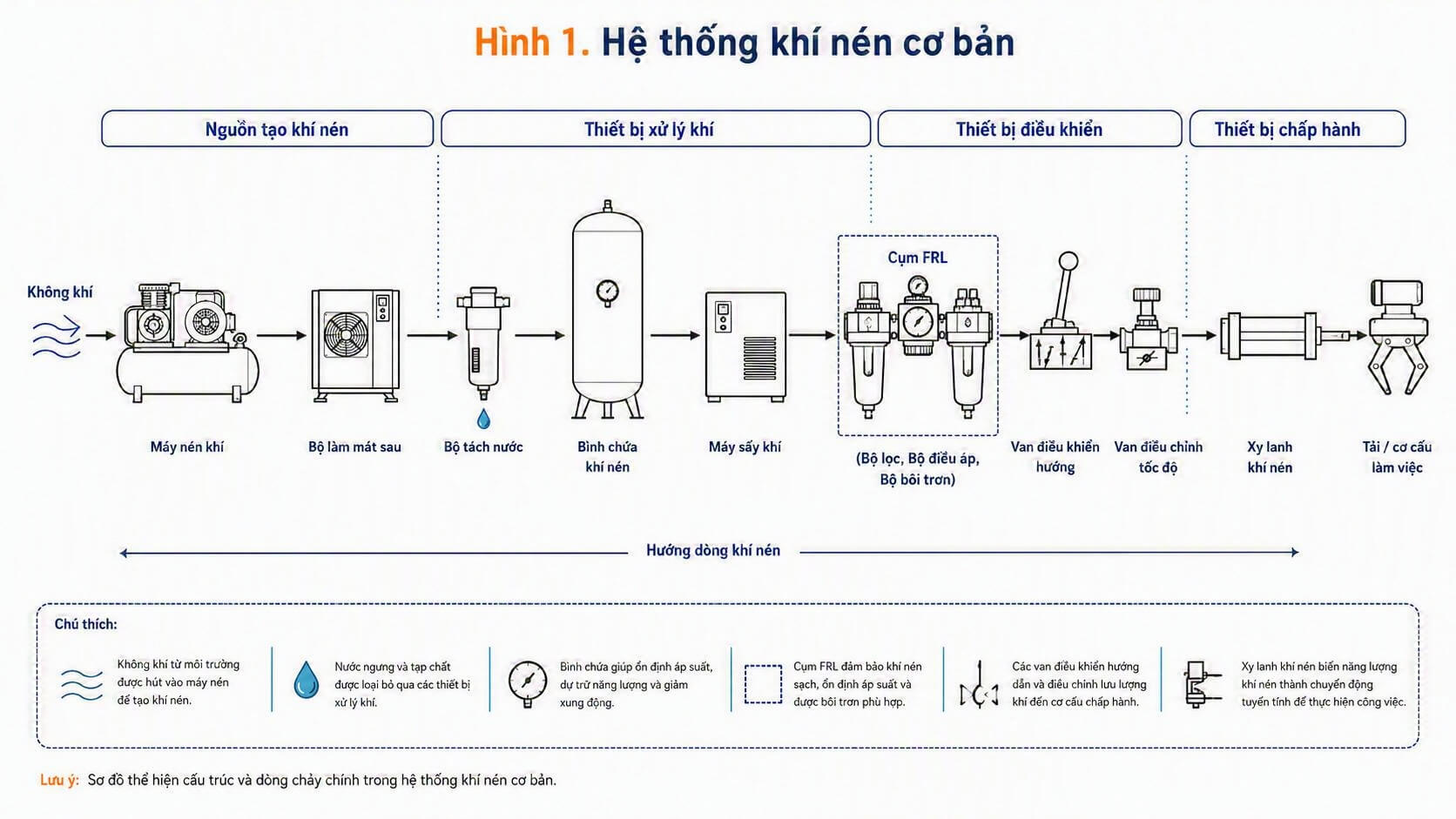
1. What parts make up a basic pneumatic system?
A pneumatic system used in an automated machine can usually be divided into 4 main groups.
Compressed-air source
→ Air-treatment equipment
→ Control equipment
→ Actuating equipment
Where:
- Compressed-air source: the compressor, the air receiver tank.
- Air-treatment equipment: the cooler, the water separator, the air dryer, the FRL unit.
- Control equipment: the directional control valve, the solenoid valve, the speed controller.
- Actuating equipment: the pneumatic cylinder or a mechanism that uses air to create motion.
Put simply, air is generated at the compressor, cleaned and pressure-adjusted, then passes through a control valve to make the cylinder extend or retract.
2. How does the airflow travel?
In a basic circuit, the airflow usually travels in this order.
Outside air
→ Compressor
→ Cooler / water separator
→ Air receiver tank
→ Air dryer
→ FRL unit
→ Directional control valve
→ Speed controller
→ Pneumatic cylinder
→ Working mechanism
Here, the point to note is that air should not be fed straight into the cylinder after being compressed.
Compressed air can contain moisture, dust, oil or contaminants in the piping. If untreated, over the long term it can jam valves, make the cylinder run unstably, or shorten equipment life.
So before the air reaches the valves and the cylinder, it usually needs to pass through the air-treatment equipment.
3. What is the FRL?
In a pneumatic circuit, the FRL unit appears very often.
F = Filter     = filter
R = Regulator  = pressure regulator
L = Lubricator = lubricator
In practice, not every system uses all 3 parts. Many devices today do not need extra oil supply, so the lubricator part may not be used.
Even so, the filter and the regulator are almost always very important parts.
The filter removes water and contaminants from the air. The regulator adjusts the supply pressure to the machine or to each mechanism group.
If the pressure is too low, the cylinder may lack force. If the pressure is too high, the mechanism may hit hard, be noisier and wear faster.
4. The control valve and the speed controller
After the air is treated and pressure-regulated, it goes to the control valve.
The directional control valve decides which side of the cylinder the air enters. With a double-acting cylinder, when the valve switches state, one side of the cylinder is supplied with air and the other side exhausts to the outside. That is how the cylinder can extend or retract.
The speed controller is used to adjust the cylinder's movement speed.
In a real machine, the speed controller is a small part but has a fairly large effect on how the mechanism "feels" running. If it is opened too much, the cylinder can run fast and hit hard. If it is choked too much, the cylinder runs slow or unstably.
5. Why do you need to read JIS symbols?
In a machine drawing, the pneumatic circuit is usually not drawn as the real shape of the equipment. Instead, standard symbols are used. 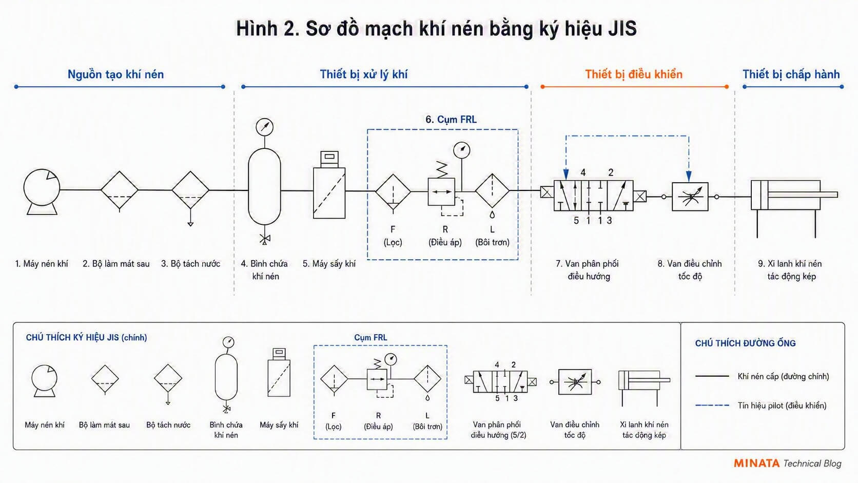
For example:
- The compressor has its own symbol.
- The filter has its own symbol.
- The regulator has its own symbol.
- The directional control valve has its own symbol.
- The speed controller has its own symbol.
- The pneumatic cylinder has its own symbol.
In a machine-design environment in Japan, these symbols are usually based on the JIS standard.
At first it can look a little hard, but if you understand the way the air travels, reading the diagram becomes much easier.
When looking at a pneumatic diagram, read it in this order first:
Where is the air source?
How is the air treated?
Which valve controls which cylinder?
Through which air line does the cylinder extend/retract?
Where is the speed adjusted?
Where does the air exhaust?
Just being able to read these points already gives you the skeleton of a basic pneumatic circuit.
6. Conclusion
This article is only the opener, to see the pneumatic system as a whole.
In machine design, pneumatics is not just "bolt on a cylinder and you're done." You need to look at the whole path of the air: from generating the air, treating it, regulating pressure, controlling direction, adjusting speed, all the way to the cylinder doing the work.
In the next articles, I will split each part out to make it easier to read, for example:
- Basic JIS symbols in a pneumatic circuit.
- How 3/2, 5/2 and 5/3 valves differ.
- How to choose a pneumatic cylinder.
- How to calculate cylinder force.
- Meter-in and meter-out in cylinder speed control.
- Common mistakes when using pneumatic cylinders in automated machines.
Grasp the whole first, then going into each detail becomes much easier.
View all MINATA technical articles