Machine Design #14: Pneumatic Symbols – How to Read the Symbols in a Circuit Diagram
In the previous article, we looked at a basic pneumatic system as a whole: from the compressor, the air-treatment equipment, the FRL unit and the control valve, all the way to the actuating cylinder.
The next step in reading the drawing is understanding pneumatic symbols.
In practice, a pneumatic diagram does not draw the equipment as its real shape. Instead, standard symbols are used to represent the air lines, the function of each device, the control method and the connection ports.
Once you get used to these symbols, reading a pneumatic circuit becomes much easier.
1. What are pneumatic symbols for?
Pneumatic symbols are used to represent:
- The main air lines
- The pilot signal lines
- The various valves
- The air-treatment equipment
- The pressure-measuring devices
- The cylinders and actuators
The key points are:
- A pneumatic symbol does not show the real shape of the device
- A symbol does not describe the physical installation layout either
- The main goal is to show the function and the relationships within the circuit
In short, a pneumatic diagram is a functional diagram, not a 3D drawing or a layout drawing.
2. A few basic symbols to remember first
When you are starting out, you do not need to memorize the whole symbol table. Just grasp the most basic groups.
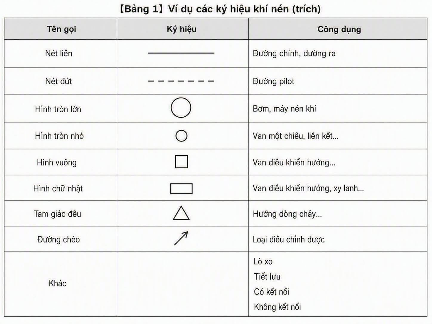
Table 1. Examples of basic pneumatic symbols commonly seen in a circuit diagram.
Among them, there are 2 very important points to remember right from the start.
A solid line is usually used for the main air line, the supply line or the outlet line.
A dashed line is usually used for the pilot line, that is, the control signal line.
Just being able to tell a solid line from a dashed line already makes reading a pneumatic circuit much easier.
3. Common pneumatic devices and their symbols
In a pneumatic diagram there are quite a few different symbols. But at the early stage, prioritize recognizing the devices that appear most often.
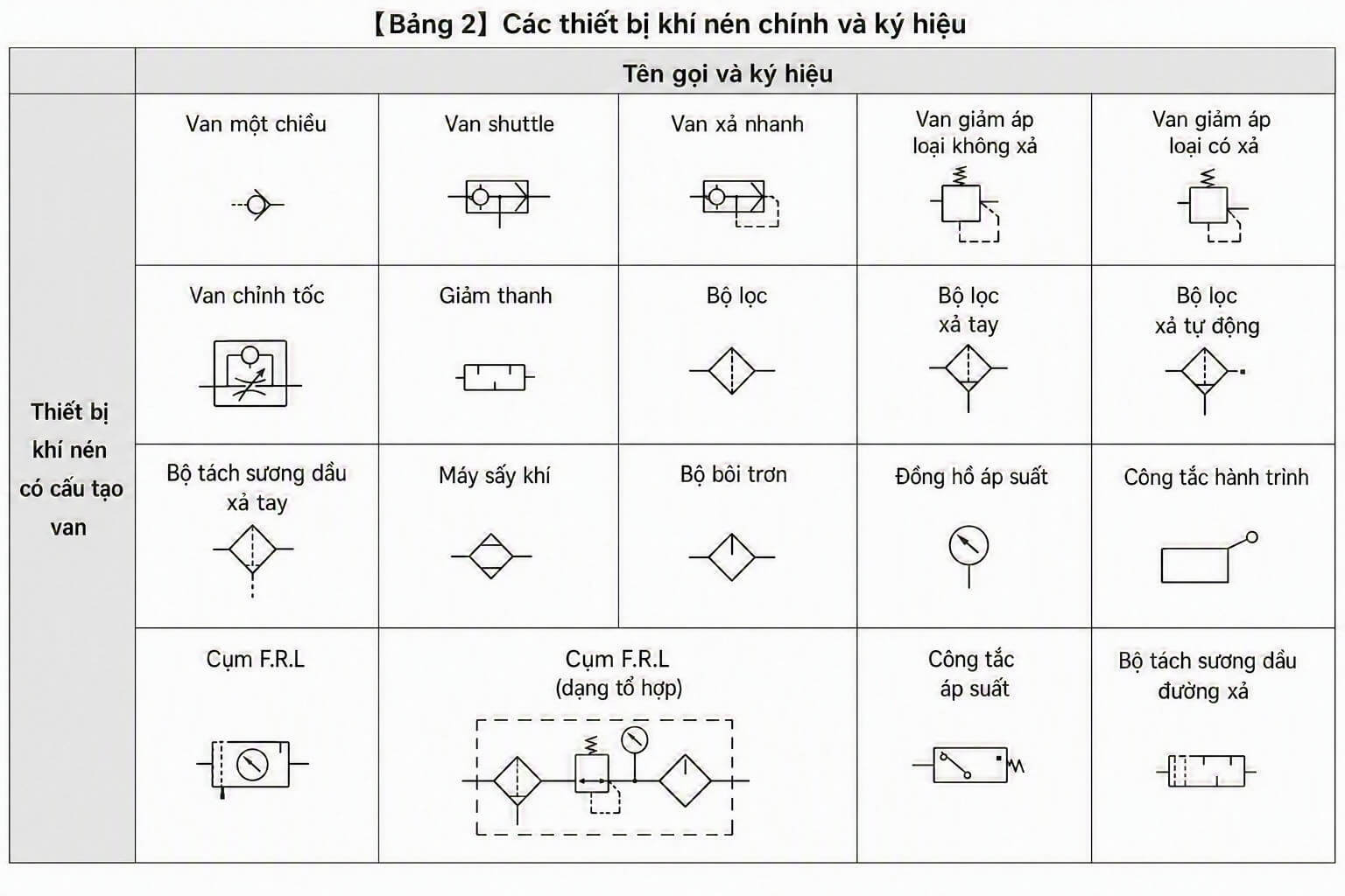
Table 2. Some main pneumatic devices and their common symbols.
If you read automated-machine drawings, the symbols you meet most often are usually:
- Filter
- Regulator
- FRL – the filter, regulator, lubricator unit
- Directional control valve
- Speed controller
- Pneumatic cylinder
You do not need to memorize them all at once. Just getting gradually familiar with the frequently appearing symbols is enough.
4. How is a directional control valve represented?
This is a very important part, because in a pneumatic circuit the directional control valve is almost the center of the control side.
Most directional control valves in practice are represented by combining:
- The basic valve body
- Squares or rectangles showing the states
- Arrows showing the direction of airflow
- A spring, push button, coil, pilot, etc., to show the actuation method
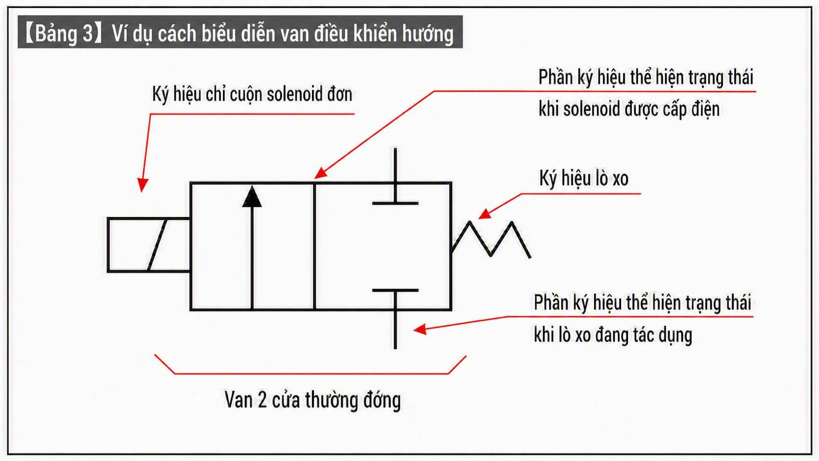
Table 3. An example of representing a directional control valve with symbols.
When looking at a directional control valve, read it in this order:
- How many ports does the valve have?
- How many positions does the valve have?
- What actuates the valve?
- Does it return by spring, or hold its state?
- In each position, which way does the air flow?
A valve symbol looks complex at first, but it is really just many basic symbols combined together.
5. From symbols to a circuit diagram
Once you understand each individual symbol, you can read a whole circuit diagram.
For example, a system using a pneumatic cylinder can be represented in two ways:
- The real image of the equipment, piping and valves
- The circuit diagram in symbols
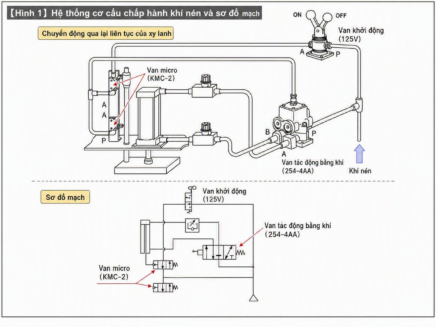
Figure 1. A pneumatic actuator system and how it is represented as a circuit diagram.
In the diagram, the real devices are reduced to symbols. The piping is drawn with solid lines, while the control or pilot signal is drawn with dashed lines.
The important thing is that the diagram tells you:
- How the air travels
- Which device controls which
- Which port is the supply line
- Which port is the exhaust line
- Where the pilot signal is acting
When you can read these points, you have started to understand a pneumatic drawing, not just "see a lot of symbols."
6. Conclusion
Pneumatic symbols are the basic language of a pneumatic circuit diagram.
At the early stage, do not try to memorize the whole symbol table. It is more important to grasp the core points:
- The main air line is a solid line
- The pilot line is a dashed line
- The diagram shows function, not the real shape
- Some symbols to recognize early are: filter, regulator, FRL, directional control valve, speed controller and cylinder
Once you are used to these symbols, it will be easier to move on to the next part: how to read directional control valves and cylinder circuits in practice.
Next in the series: Machine Design #15: Pneumatic directional control valves – How to read 3/2, 5/2 and 5/3 valves
View all MINATA technical articles