Device Selection #16: Toggle Clamp, Air Clamp or Screw Clamp — Choosing by Force, Cycle and Handling
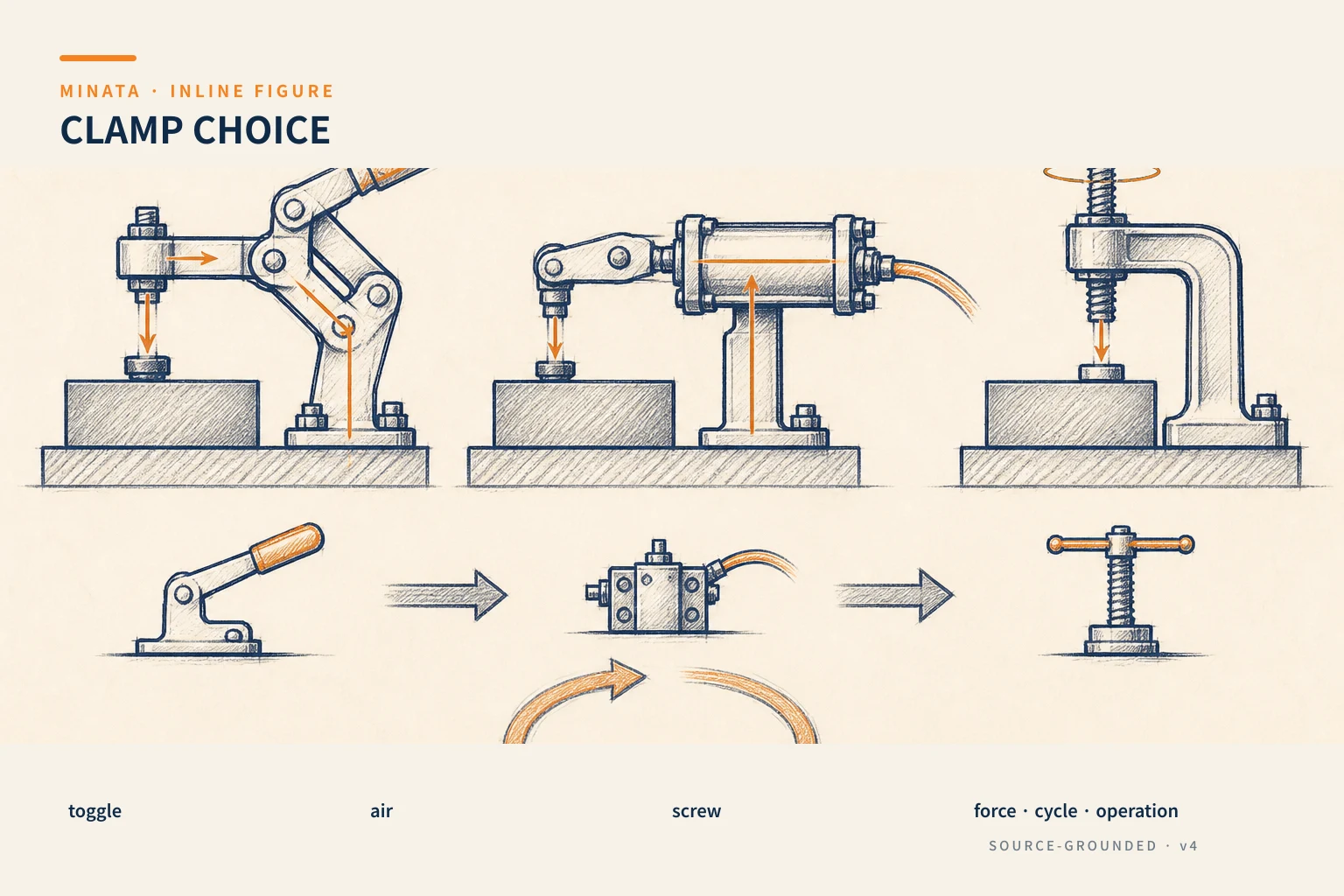
Short answer: choose a toggle clamp when the operator needs to clamp/release quickly by hand with a repeatable position; choose an air clamp when the cycle must be automatic and the clamping force and sensor state must go into the PLC; choose a screw clamp when you need an adjustable force, flexibility for set-up or low volume. A clamp is not used to define the workpiece position. It must press the workpiece against the previously designed pins and rest faces, with enough force to resist the reaction but without bending, marking or losing the datum.
Quick comparison
| Criterion | Toggle clamp | Air clamp | Screw clamp |
|---|
| Handling method | Hand, via an over-center mechanism | Air valve/cylinder, can be automatic | Hand tighten/wrench/screw |
| Cycle | Moderate, fast repeated handling | Automatic cycle, many clamp points | Set-up, testing, small batch |
| Force and stroke | By model and lever arm | By bore/pressure/mechanism | Wide adjustment, depends on who tightens |
| Feedback | Observation or an added sensor | Easy to fit a sensor/interlock | Usually checked manually |
| Main risk | Hand strike, lever stroke, overload | Air loss, wrong clamp sequence, moment load | Non-repeatable force, time and handling error |
Locate first, clamp second
A good fixture separates the two roles. The rest face and pins bring the workpiece to the datum; the clamp creates the force holding the workpiece against those datums. If the clamp is used to pull the workpiece sideways to the pin, the friction force, burr and user handling will change the position. If the clamping force presses on an area with no support, a thin sheet can sag and then spring back when removed, making the machining/measurement operation wrong even though the pin is still correct.
Before choosing a clamp, draw the reaction force from machining, pushing, vibration, gravity or a spring. Determine the clamp point, the force direction and the support point on the opposite side. The clamping force must resist the force tending to move the workpiece off the reference, with a reasonable margin for the process; it is not a goal of the-larger-the-better. Plastic, thin aluminum, a finished surface or a painted part may need a pad, soft jaw or a force limit.
Toggle clamp: fast and intuitive for hand handling
A toggle clamp uses a lever mechanism through an over-center point to hold the clamped state. It suits assembly jigs, inspection fixtures, light drilling/punching, welding fixtures and semi-automatic handling where the user needs to open/close quickly. DESTACO notes that toggle clamps come in many manual, hydraulic and pneumatic configurations; the manual quick-action type is chosen by the mounting type, holding force, opening clearance and handling behavior.
Choose a vertical hold-down, horizontal hold-down, push-pull or latch type by the force direction and space. Do not take the catalog holding capacity and then clamp in any direction. Look at the force-application point on the arm, the stroke, the lever opening angle, the workpiece-loading clearance and the side-load limit. If the part is loaded by a robot or a person's hand passes through the clamp zone, the arm's travel path is a real safety/ergonomics requirement.
Adjust the spindle pad so the clamp closes at the correct over-center position and creates force on a supported area. Too long a spindle makes the arm elastic; a small pad marks the surface; a mechanism mounted on a thin plate deforms the whole assembly. For a long-life jig, consider pad replaceability, the pivot bushing and checking play. A toggle clamp is very effective when the process does not need the PLC to know each state; if an interlock is needed, add a sensor/limit switch per the machine architecture.
Air clamp: for an automatic cycle with a controlled state
An air clamp can be a pneumatic toggle clamp with an integrated cylinder, a swing clamp, a link clamp or a cylinder combined with a lever mechanism. It suits when many clamp points must run in sequence, when people must not enter the danger zone, or when a robot loads the workpiece. The valve, regulator, position sensor and PLC must be treated as part of the clamp, not accessories fitted afterward.
An air clamp's force depends on the pressure at the point of use, the piston area, the advance/return direction, the mechanism loss and the friction. The catalog force usually must be read with the pressure/lever condition. Check the lowest pressure while other mechanisms run at once, the piping, the valve and the clamp state when the air supply is lost. If air loss can drop the workpiece or cause a tool collision, you need added safety logic, a mechanical lock or a load-holding approach suited to the risk assessment.
A clamp-open/clamp-closed sensor is valuable in an interlock: the machine runs only when the workpiece is present and the clamp confirms the correct state. However, the sensor reports that the piston/clamp has reached position; it does not by itself prove the clamping force is enough or the workpiece is on the correct datum face. When clamp quality is critical, you may need pressure monitoring, a force sensor or a mechanical poka-yoke depending on the risk.
An air clamp is not always cheaper than a toggle clamp when counting the FRL, valve, manifold, cable, PLC I/O, commissioning and maintenance. Its value lies in reducing handling time, repeating a sequence, protecting people and opening the way to automation. The number of cycles, the model-change time and the traceability requirement tell you when the investment is justified.
Screw clamp: flexible for set-up and adjustable force
A screw clamp includes a strap clamp, step block, toe clamp, vise, screw clamp or a custom screw-based mechanism. The adjustable force and flexible configuration make them suit a prototype, a frequently changed fixture, a CNC set-up or a small batch. It is also useful when you need to clamp in a tight space or a force in a special direction that a standard toggle does not fit.
The disadvantage is that the handling time and force repeatability depend on the user, the thread, the lubrication, the wrench and the procedure. The tightening torque does not translate into a fully fixed clamping force because the thread/seat friction changes. If the force must be controlled, use a torque tool, a washer, a mechanical stop or a suitable measuring device rather than telling the operator to "tighten by feel."
A screw clamp also creates a large force that can easily damage the workpiece or plate. Ensure the clamp strap rests on the correct step/step block, the force line points toward the support point and the part is not pulled off the pin. Do not let the thread become a locating stop; use a separate locator and stop so the load/unload handling does not lose the reference.
Choosing by cycle, model change and safety
For a single-piece inspection fixture, a toggle or screw clamp may suit better than an air clamp because it is easy to see and easy to adjust. For a robot station or a machine with an interlock, an air clamp usually creates a safer sequence, but the fail state must be designed. For many models, quick-change pads, a changeable arm and the sensor position may matter more than increasing the clamp force.
Assess the design in the worst-case state: a thick/thin workpiece within tolerance, burr, a person placing it off-position, low pressure, a worn clamp or a faulty sensor cable. The clamp must not strike the workpiece when opening, not block the workpiece-removal path and allow cleaning. If using a machine tool, check the jig body stiffness, the reaction force and the chip evacuation; a compact clamp placed in the tool path is still a design mistake.
The selection process
- Define the datum/rest face/pins first; decide which datum the clamp only presses the workpiece against.
- Record the reaction force, force direction, clamp position, contact area and surface-deformation limit.
- Choose a manual toggle for fast handling; a pneumatic air clamp for an automatic sequence; a screw clamp for a flexible set-up/small batch.
- Check the holding force, stroke, opening angle, side load, handling space and pad replaceability.
- For pneumatics, check the lowest pressure, valve, sensor, interlock and the state on air loss.
- Test with the worst-tolerance workpiece and the real operator/robot procedure.
Common mistakes
- Using the clamp to pull the workpiece into the datum instead of pressing it against the datum.
- Choosing a large force and deforming a thin workpiece.
- Ignoring the toggle arm's travel path and the workpiece-removal clearance.
- Using only a closed sensor to infer the clamping force/correct workpiece position.
- Using an air clamp without designing the air-loss state or a safe sequence.
- Using a screw clamp at a high cycle then expecting the force/day to repeat the same.
Designing the contact area and the force line
The clamp pad must be placed on an area with enough stiffness and a support underneath. For a finished part, use a replaceable pad, polymer or a suitable soft metal to avoid marking; but a soft pad also changes the force and position, so it must be tested against the real measurement requirement. The clamp direction should push the workpiece down onto the rest face and toward the stopper, avoiding a force component that pulls the workpiece off the pin.
Multiple clamp points must have a sequence. Clamping one side first can rotate the workpiece, then the second point only locks that deformation. For an air clamp, the PLC should control by a tested sequence, checking the feedback and timeout; for hand operation, the jig should use geometry/poka-yoke that makes the correct sequence natural. Opening the clamp must also be considered: does the workpiece have spring-back, is it oily, can it drop or be held back by a tool?
A clamp wears at the pin, pivot, spindle, thread and pad. Put a force/stroke check in the periodic maintenance, keep spare pads/spindles if they affect quality. A clamp that no longer reaches over-center, or a misaligned sensor, should be treated as a functional fault, not a minor part that can be ignored.
Before release, test the open–load workpiece–clamp–machine/inspect–open operation with real users. Measure the time, check for hand/robot strikes, check whether the workpiece rests on the full datum, and observe the pad after the repeated cycle. This real result often reveals a mis-placed pad, an obstructing arm or a clamping force deforming the part earlier than any 3D drawing.
Save the result in the fixture acceptance file so the next model change has clear reference data.
Quick selection checklist
- [ ] Do you have the datum, rest face and pins for the clamp to press the workpiece against the correct reference?
- [ ] Do you need fast, fixed and intuitive hand handling? Yes → consider a toggle clamp.
- [ ] Do you need PLC control/feedback, an automatic cycle or a robot? Yes → consider an air clamp with valve/sensor/interlock.
- [ ] Do you need set-up flexibility or an adjustable force for a small batch? Yes → consider a screw clamp with a tightening procedure.
- [ ] Have you checked the reaction force, workpiece deformation, clamp-opening path and the energy-loss state?
MINATA can review the jig layout, clamping force, sequencing and the operation/maintenance capability before the machine team locks the clamping device. Talk to the Engineering & Manufacturing team.
References
View all MINATA technical articles