Device Selection #22: Casters, Adjusters or Leveling Feet for a Machine
Choose casters when the machine must move frequently along a defined route; choose adjusters/leveling feet when the machine must stand stable and level at a position; choose a system with casters + lowering/leveling feet when you need both modes. The correct decision is based on the total load, the real load distribution, the floor, the pull/push method, the dynamic force, vibration, locking and the mode-change handling. A wheel that "can take the total mass" may still be hard to roll, lock incorrectly, or make the machine vibrate during operation.
Quick comparison
| Solution | When suitable | To check | Common mistake |
|---|
| Fixed caster | Straight movement, needs to keep direction | Layout with swivel casters, the run path | Using only fixed casters and then finding it hard to turn the machine |
| Swivel caster | Needs to change direction, turn on the spot | Turning radius, caster offset, push force | Too many swivel casters make it hard to steer |
| Braked/locking caster | Temporary stop while moving | Lock type, floor surface, lock purpose | Treating the caster brake as a machine anchor or a safety device |
| Adjuster/leveling foot | Machine placed fixed, needs leveling | Thread, compressive load, pad, floor, anti-vibration | Leveling by thread on a weak floor or not locking the setting |
| Casters + lowering feet | Machine must move then operate stable | Lift/lower mechanism, sequence, clearance | Leaving the operating load still on the wheels |
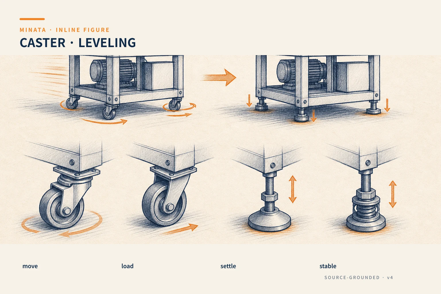
Define the two modes: moving and operating
Clearly separate the state where the machine is being repositioned from the state where the machine is producing. When moving, the center of gravity, pull/push force, slope, door thresholds, floor gaps, speed and the operator decide the wheels. When operating, the dynamic load from the cylinder, axis, conveyor, robot, door or operator decides the base, the frame stiffness and the vibration. A good approach describes where the machine rests in each state, who handles it, what tools are needed and how to prevent putting the machine into a cycle when the feet are not lowered.
Record the total mass including the frame, panels, electrical cabinet, bought-in equipment, maximum workpiece, fixture, consumables and future options. The center of gravity may not be in the middle if the robot, feeder or electrical cabinet is on one side. The load on the wheels/feet is not shared equally just because there are four positions; the floor error, frame stiffness and center-of-gravity position make one or several points take a higher load. Use the ideal number of supports to start, then add a factor suited to the real condition and check the worst load case.
If the machine is lifted by a pallet jack, forklift or crane, those actions can create a different load from the operating casters. Determine the lifting point, lifting speed, the lock/anchor during transport and the accessories to remove. Do not choose casters to replace the lifting point or use a caster as a towing hook if the manufacturer does not allow it.
Read the load capacity under the manufacturer's condition
A caster's load capacity is published under a defined test condition, including the speed, floor type, temperature, obstacles and running method. Blickle describes the load test for transport wheels/casters per DIN EN 12532 / ISO 22883 with standard conditions; it also emphasizes that the required load capacity must be based on the equipment weight, additional load, number of casters and a safety factor for non-standard conditions. So the catalog number is an input, not a license to run on every floor.
In the calculation sheet, separate the total static load, the goods/fixture load, the lateral pulling force, the slope, the threshold impact, the uneven floor path and the acceleration/deceleration. Choose each caster's capacity by the manufacturer's method and the layout condition, considering the situation of one wheel losing contact or the load skewing when the floor is uneven. If a four-wheel machine has an uneven frame, three wheels can take most of the load; if the machine has adjuster feet that lower, the loading when lowered and during the transition must also be checked.
Do not use the load unit or speed rating from another series. The bracket, wheel, axle, bearing and brake form an assembly; changing just the wheel, fork or bolt can change the capacity. Lock the full part number, the mounting face, the hole pattern, the fastener and a washer/plate suited to the frame foot.
The floor surface decides the diameter, tread and push force
A caster that rolls smoothly on flat epoxy can vibrate and be hard to push on a floor with gaps, broken tiles, thresholds or a surface with chips. Survey the movement route: floor material, steps, slope, joints, drainage gaps, doors, elevators, turning clearance and the stopping place. If you must cross an obstacle, check the manufacturer's rule on wheel diameter, tread hardness and load under that condition; do not infer the number from the feel of pushing an empty machine.
The wheel/tread material affects the rolling force, durability, marks on the floor, noise, oil/chemical resistance and static electricity. Polyurethane, rubber, nylon, cast iron or a special material have pros/cons by the floor and environment. Choose the material only after knowing the floor, oil, water, heat and the area's clean/ESD requirement. Writing "PU wheel" without the hardness, size, bearing, bracket and environmental condition is not enough to order.
A larger wheel diameter usually helps cross obstacles and reduces rolling resistance in many conditions, but increases the machine height, the center-of-gravity point and the wheel space. Check the caster height/overall height, swivel radius, wheel sweep and the clearance with the panel/guard. A swivel caster that hits the frame foot or the door right when it turns 90 degrees is a layout mistake, not an installation mistake.
Arranging fixed and swivel casters to control direction
Fixed casters create the direction, swivel casters create the ability to change direction. The arrangement depends on the machine's rectangle, the dominant movement direction, the frame length/width, the handle position and the operator's capability. Two fixed casters on one side and two swivel on the other is a common configuration for a cart along a route; but do not copy that configuration for every machine because it may not suit the turning/approaching-the-fixture need.
Too many swivel casters can make the machine "drift" in direction, need a large initial force for the forks to self-orient, or change direction unexpectedly when the floor has a slope. Too many fixed casters make the machine hard to turn. If moving by a tugger, check the pulling force at the drawbar, the turning radius, speed, doors and the vehicle's emergency-stop case. If pushed by hand, assess the ergonomics, the force needed and the visibility; this is a real-work question, not just the wheel size.
When the frame has more than four caster points, the suspension/compensation method must be designed to distribute the load. Six wheels rigidly mounted on a frame can leave one wheel hanging when the floor is uneven. Put the load-sharing/rocker/leveling requirement into the design rather than adding wheels for "peace of mind."
Brakes, directional locks and their limits
A brake wheel, total lock and directional lock are different functions depending on the design. A brake can brake the wheel; a total lock can lock both the wheel and the swivel; a directional lock orients the caster for straight running. Read the catalog of the exact part number to know the function, how to operate it and the allowable load. Test it when the floor has dust/oil and when the machine is fully loaded; the lock mechanism must be easy to operate, not under a closed panel or next to a hand-pinch zone.
A caster lock is for temporarily holding the position per the manufacturer's condition, not to replace a machine anchor, leveling foot, safety brake or a lockout measure. Blickle warns that a locking caster is not intended to secure the load during transport on a truck/vehicle or similar. For a machine that vibrates, cuts, presses, has a robot or a lateral force, the operating load must go into the foot/anchor mechanism by design rather than being placed on the wheel brake.
Define on the HMI/procedure: the machine may run only when the feet are lowered, what state the caster brake is in, which door/guard must be closed, and who confirms. If using a sensor to confirm the feet are lowered or the lift module, check the fail-state logic and the mechanical blocking mechanism. A color/status light supports the handling, but does not replace the safety control from the risk assessment.
Choosing adjusters and leveling feet
An adjuster consists of a stem/thread, base/pad, nut/lock and sometimes an anti-slip layer or a vibration-damping element. Choose by the compressive load, thread size, the required adjustment height, the pad area, floor compatibility, environmental resistance and how to lock the setting. Do not use a large thread travel to compensate for an excessively sloped floor; the machine can become unstable, the frame can twist, or the height can change the mechanism's line of action.
A large base can help distribute the pressure onto the floor, but the choice also depends on the floor material and load. An anti-slip pad can increase grip in suitable conditions, but does not replace the decision to anchor the machine when there is a dynamic force or a slip risk. For an epoxy floor, a concrete base, grating or a floor with drainage, choose a suitable pad/mounting and confirm the factory's requirement. If anchoring is needed, the layout must leave a hole/plate and consider the ability to remove the machine later.
Anti-vibration feet are only effective within the load/frequency range and construction the maker publishes. Placing an isolator under the machine but with a stiff pipe/cable tray connecting to another structure can create a different vibration transmission path. Before choosing anti-vibration feet, determine the vibration source, the target to reduce, the frame stiffness and the transmission through the utility; do not write "rubber vibration damping" as a general solution.
The hybrid system: move, then set the machine down on feet
For a small cell that must change place but stand firm during operation, a caster + adjuster system or a retractable caster is a reasonable choice. The operating state must clearly transfer the load from the wheel to the feet; check the clearance so the wheel has no load, or only the load by design. The lift/lower mechanism can be a screw, cam, pedal, cylinder or lift module; each needs consideration of the operating force, load, self-locking, travel limit, pinch point and maintenance.
Do not choose a hybrid system just for "convenience." It adds handling, a mechanism, height, cost and failure modes. Build the sequence: unlock, raise the feet, move, position, lower the feet, level, confirm, then enable the machine. At a place with a height difference, determine how much can be adjusted and who is allowed to do it. If there is a stiff utility, check the hose/cable length and the disconnect procedure before moving.
Handover and maintenance
The machine file must state the total design load, the caster/feet position, model, load rating, wheel/tread, brake type, fastener torque, movement route, lifting point and the mode-change handling. Label the load/direction where needed, especially with a handle, lift point or directional caster. Instruct the operator not to pull the machine from a panel, cable tray or guard.
The inspection schedule includes wheel wear/cracks, bearing, axle, swivel, fastener, brake, tread with foreign matter stuck, adjuster height and floor indentation marks. If the rolling resistance increases, find the cause such as trapped chips, a wheel flat spot, a broken bearing, floor degradation or an overloaded caster; do not increase the pulling force by a person. When replacing a caster, use the exact model/rating or reassess the whole assembly.
The selection process
- Separate the moving and operating states; build the load case, center of gravity, route, floor, speed and operator.
- Choose the number of supports/fixed–swivel arrangement or feet; compute the load per point by the exact manufacturer's guidance.
- Choose the wheel diameter, tread, bearing, bracket and brake by the floor, environment, obstacle and push force.
- Choose the adjuster/base/anchor or hybrid system by the stability, level and vibration when the machine runs.
- Check the layout: bolt pattern, swivel sweep, overall height, door/panel clearance and lifting point.
- Test fully loaded on the real route, then test the machine running on the feet; hand over the SOP and inspection schedule.
Common selection mistakes
- Dividing the total load by four and using that number per caster without considering the skewed load and floor.
- Choosing a caster by the thread/plate size without looking at the load, wheel, tread and speed rating.
- Skipping the survey of door thresholds, slope, floor joints and turning radius.
- Using a caster brake to take the operating force or to hold the machine during transport.
- Letting the machine run while the load is still on the wheels.
- Using an adjuster to fix a twisted frame, a weak floor or an uncalculated dynamic load.
Checklist before locking the BOM
- [ ] Do you have the total load, center of gravity, moving/operating load cases and the real number of supports?
- [ ] Has the caster/feet load capacity been cross-checked against the maker's test condition and safety factor?
- [ ] Have the floor, thresholds, slope, route, push/pull force, wheel diameter and tread been checked?
- [ ] Do the fixed–swivel arrangement, brake/lock, swivel sweep and height suit the layout?
- [ ] Do the adjuster/leveling foot/anchor take the operating load instead of the wheels when the machine runs?
- [ ] Have the move–operate SOP, lifting point and maintenance plan been handed over?
MINATA can work with the machine team to review the load case, route, base layout and a push-force test before locking the BOM. Talk to the Engineering & Manufacturing team.
References
- MISUMI, Factory Automation Catalog 2018, Casters / Adjuster Pads chapter; cross-checked against MINATA's internal catalog on 2026-08-23.
- Blickle, Dynamic & static load capacity, referencing how to determine the wheel/caster load from the equipment load, additional load, number of supports and operating condition.
- Blickle, Wheels & Castors Classification, referencing the load test condition per DIN EN 12532 / ISO 22883.
- Blickle, Product safety, referencing the usage limit of a locking caster and the effect of non-catalog conditions.
View all MINATA technical articles