Device Selection #10: Pneumatic, Electric or Hydraulic Actuator — Choosing by Force and Control
Short answer: a pneumatic cylinder suits fast out-and-back moves, clear end points and a simple mechanism; an electric actuator suits when position, speed, force or the motion profile needs to change by program; a hydraulic cylinder is considered when the force is very high, the load is heavy and the machine environment suits a pressurized oil system. The right choice starts from the force at the working head, the stroke, how it must stop and the number of cycles — not just from the actuator type already in the workshop. You must also account for the accompanying system: pneumatics needs air quality and valves; electric needs a motor/driver/cable; hydraulics needs a power pack, valves, hoses and leak management.
Quick comparison
| Criterion | Pneumatic cylinder | Electric actuator | Hydraulic cylinder |
|---|
| Suitable motion type | Two points, repeat cycle, may have a stopper | Position/speed/force by profile | High force, pressing, lifting, heavy load |
| Position control | End of stroke or a dedicated air-servo solution | Programmable, with feedback depending on configuration | Controllable by valves and feedback, a more complex system |
| Energy source | Treated compressed air | Electricity and driver | Pressurized oil, pump and valves |
| Strength | Compact, fast response, familiar mechanism | Flexible, repeats profiles, digital integration | High force density, suits large loads |
| What to account for | Compressibility, air quality, exhaust noise | Motor/screw sizing, cable, tuning | Oil leaks, heat, hoses, maintenance and pressure safety |
| Example | Clamp, push, stop, simple pick-and-place | Slide, press by recipe, format change | Press machine, lift table, heavy-load mechanism |
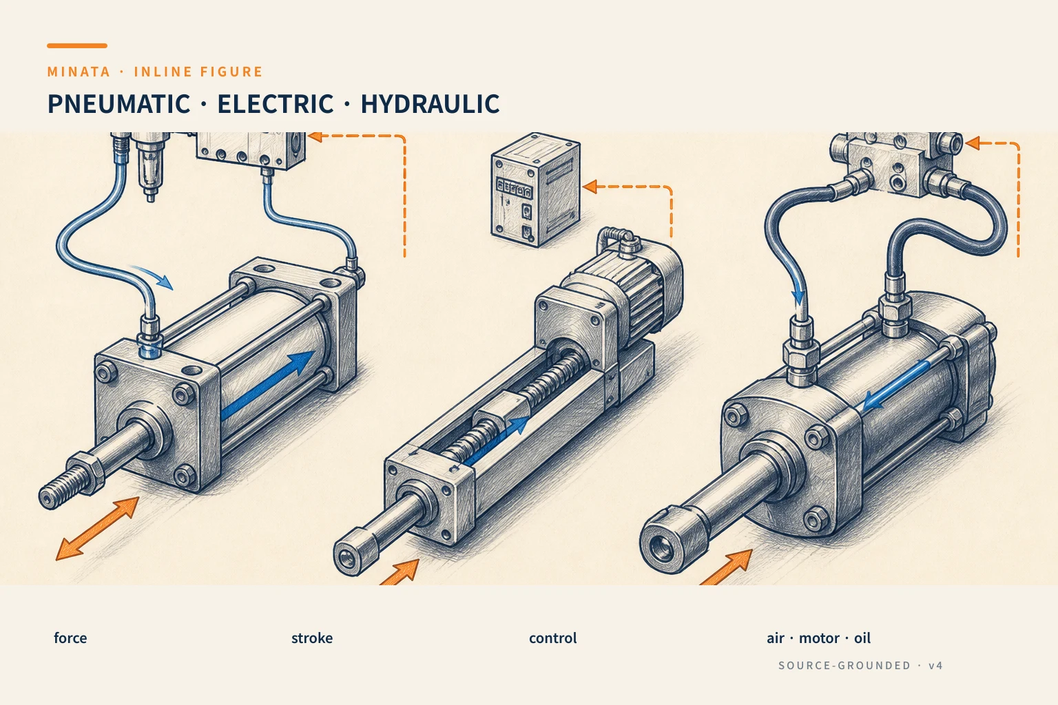
What does the working head need?
Before naming the device, describe the job with verbs and quantities: push a box to a stopper, clamp a workpiece, press a pin, lift a fixture, move a camera head, close a mold, or open a guard. Then record the force needed at the working head, the force direction, the stroke, the speed, the cycle, the varying part of the load and the position accuracy. Two often-missed questions are "at which point of the stroke is the force needed?" and "what happens when the supply is lost?".
Force does not come from mass alone. Rail friction, an incline angle, cutting force, a return spring, vacuum, eccentricity and the inertia during acceleration can all appear. For a pressing mechanism, the contact force at the end of stroke can differ greatly from the force to move empty. For a clamp mechanism, you must distinguish the force the cylinder produces from the real force transmitted to the part after the lever mechanism. This decides the piston diameter, screw lead, gearbox or system pressure later.
Pneumatic cylinder: effective for a move with a clear end point
Pneumatics is common in automated machines because the cylinder, directional valve, magnetic sensor and accessories form a familiar, easy-to-maintain system. For an action that only needs advance/retract, clamp/open, raise/lower a short distance or separate a product, a double-acting cylinder gives a practical choice. It also has the natural "softness" of compressed air, sometimes useful when contacting a workpiece or reducing impact with proper cushioning.
The core disadvantage is that air is compressible. So holding an accurate intermediate position or controlling force/velocity really stably requires more control elements, sensors and algorithms than an ordinary on/off valve. If the problem needs several stopping points or changing the stroke by recipe, do not expect that just adding one sensor turns a two-position cylinder into an electric axis. Reassess an electric actuator, or use a dedicated pneumatic solution when the task genuinely fits.
When sizing a cylinder, compute the force from the machine's working pressure and the piston's effective area, then account for seal friction, guide friction, pipe loss and external forces. The rod diameter makes the effective area on the return side smaller than the advance side; pull force and push force therefore need separate checks. Using the compressor's nominal pressure to conclude the force often leads to a marginal choice: the pressure when many mechanisms run at once, the filter-regulator, the pipes and the valves are the real working conditions.
A long stroke, an eccentric load or a heavy tool head needs external guide rails or a cylinder with integrated guiding. The cylinder rod must not be assumed to be a moment-bearing guide rail. If the fixture is off-center, the lateral force wears the seal, causes binding and shortens life. Determine the moment loads Mx/My/Mz per the manufacturer's documentation, the load-center position and the mounting orientation before locking the model.
The cylinder speed is decided by the flow and the load. The one-way flow-control valve, hoses, fittings and cushioning must be chosen as a system. Closing a valve too tightly to "slow it down" can make the cycle erratic with load; letting the mechanism slam at the end of stroke damages both the fixture and the sensor. You must design end-of-stroke cushioning, a mechanical stopper or shock reduction to match the real mass and speed.
On cylinders with a magnetic piston, a magnetic sensor is a compact way to signal position. It tells you the piston has passed the sensor's mounting zone; it does not replace a continuous position measurement. The article #05 on cylinder position sensing explains when to use a magnetic sensor, a limit switch or an external proximity sensor.
Electric actuator: for motion with a "recipe"
An electric actuator can be a rod actuator, an electric cylinder, a slide with a ball screw/timing belt, or a motor–gearbox–transmission assembly designed by the machine builder. When paired with a driver and suitable feedback, it lets you set the position, velocity, acceleration, torque limit and a step-by-step profile in the program. This is useful for a multi-model machine, a pressing mechanism with several depths, an axis that changes distance by product size, or stopping points that must repeat.
The flexibility comes with a more careful sizing requirement. From the linear force and speed, you must convert through the screw lead or pulley diameter to get the motor torque and speed. From the mass and acceleration profile, you need the load inertia. Then check the continuous torque, peak torque, speed, screw/belt life, axial load and moment load on the rail. Choosing an electric actuator with "enough static force" but not enough torque during acceleration is a common mistake.
For a pressing task, state clearly whether you need position, force, or both. Motor torque-limit control can be part of the solution, but the real force at the working head is also affected by friction and the transmission. When force is a quality characteristic, consider a force sensor, a calibration approach and anomaly-detection logic. When the requirement is only to reach a mechanical stop, a simple electric actuator may suit better than a full servo system.
An electric actuator also does not solve a hanging load on power loss by itself. Many servos have an optional holding brake, but the holding brake must be chosen by the torque at that position and the safety task. For a person-lifting mechanism, a large load or a drop hazard, you need a machine-level safety assessment, a braking/mechanical mechanism and the applicable standard; do not hand the whole responsibility to one motor brake.
Hydraulics: start from the large load and the whole power station
Hydraulics transmits force through pressurized oil. For a press, lifting a heavy load, high-force clamping and mechanisms needing high force density, it is a familiar technology. Oil is less compressible than air, so the system can produce large forces and control motion through suitable valves. However, "choosing a hydraulic cylinder" means also choosing the power pack, pump, oil tank, filter, safety valve, control valves, hoses, fittings, cooling and the maintenance procedure.
The force, working pressure, piston and rod diameter must be computed together. A cylinder's rated pressure is not a pressure that can be assumed for every element. The safety valve, hoses and fittings must have a suitable pressure range. A hanging load or a load that can self-run needs a load-holding valve, a counterbalance valve or a braking architecture suited to the motion direction. When the supply is lost or a hose fails, the mechanism's safe behavior must be defined from the start.
Heat and oil cleanliness are part of the design, not an item after installation. Viscosity changes with temperature; dirty oil increases wear of valves, pumps and seals; oil leaks affect safety, hygiene and the environment. If the machine is in a clean area or near sensitive products, put the oil-leak risk and the containment approach into the decision table from the concept stage.
Hydraulics may still need position or pressure feedback. A stroke sensor, a linear encoder, a pressure transducer and proportional-valve control can create well-controlled motion, but the complexity, commissioning and maintenance rise. Use a control level proportional to the application's value; a high-force press may need it, while a simple pusher usually does not.
Comparison by five decision questions
1. How many points does the motion have, and does it change by product? Two clear points repeated many times leads you to pneumatics. Many points, a soft path, axis synchronization or a recipe change leads you to electric. Hydraulics stands out when force/load is the main constraint.
2. Which force must be controlled? A simple clamp usually needs an adequate, reliable force. A press with a quality criterion may need force measurement. A large load may shift the focus to piston diameter, pressure and hydraulic-system safety.
3. What infrastructure does the machine already have? A factory with clean, well-maintained compressed air makes air cylinders attractive. A machine with a servo cabinet, a motion network and a model-change need benefits from electric. A team experienced with power units can exploit hydraulics effectively for large machines.
4. What constraints does the environment impose? Dust, water, heat, explosive areas, food, cleanrooms and noise limits all change the choice. Do not just check the actuator's IP; also check the cable, connectors, valves, hoses and lubricant.
5. What does the mechanism do on a fault or energy loss? The default state of the air valve, the ability to exhaust pressure, the electric brake, the load-holding valve, the mechanical stopper and the safety interlock all need to be recorded in the machine sequence. This is a question to lock together with the safety review.
Three real situations
Clamping a part before machining. If it is only open/clamp, the required force is stable and the cycle is high, an air cylinder with a confirmation sensor and a rigid fixture is the practical choice. You must check the clamping force at the lowest pressure and the machining reaction force; do not choose by a bore diameter that "looks big."
A table adjusting distance by several product sizes. An electric actuator with a suitable screw/rail lets the PLC call the position by product code, adjust the advance speed and read an alarm. You must set a home, soft/hard limits, guard the rotating parts and assess pinch points.
A large-load mold press. Hydraulics may suit because the force is on a different level. The design must go beyond the cylinder: define the safety valve, the load-holding mechanism, the filter, the oil temperature, the safety cabinet and the leak-handling procedure. This is where testing under load and safety acceptance have great value.
Common selection mistakes
- Treating the nominal force as the force at every moment. With pneumatics, the real pressure and the rod-side area differ; with electric, the torque also depends on speed; with hydraulics, the system pressure must be controlled.
- Using the cylinder rod as a guide rail. An off-center load makes the system develop play and bind early.
- Comparing purchase cost while ignoring infrastructure cost. Valves/hoses/air, driver/cable or power pack/filter are all part of the total cost of ownership.
- Not describing how it stops safely. A mechanism can run well in the normal cycle but be dangerous when exhausting pressure or on power loss.
- Separating the actuator from the fixture. The rail, coupling, moment load, mechanical stop and sensor are what decide the real life.
Quick selection checklist
- [ ] Do you have the force, stroke, speed, cycle and load direction at the working head?
- [ ] Only two end points, and a fast simple mechanism needed? Yes → consider a pneumatic cylinder.
- [ ] Position/speed/force changing by recipe or several stopping points? Yes → consider an electric actuator.
- [ ] Very high force, heavy load as the main constraint, and the capability to manage an oil system? Yes → assess hydraulics.
- [ ] Have you checked the guiding, moment load, cushioning/stopper and environmental conditions?
- [ ] Have you defined the safe state on power loss, air loss or a hose failure?
MINATA can review the force, fixture, control and safe state with the machine team to choose an actuator that actually runs in the production cycle. Talk to the Engineering & Manufacturing team.
References
View all MINATA technical articles