Device Selection #05: Cylinder Position Sensing — Reed/Magnetic, Limit Switch or Proximity?
If you only need to know that an air cylinder's piston has reached the end of stroke, prefer a magnetic sensor mounted directly on the cylinder body when the cylinder has a magnetic piston and a suitable mounting groove. Choose a limit switch when you must confirm that a mechanism has actually reached a mechanical point, or when the position to be checked belongs to an assembly with no magnet; choose an inductive proximity sensor when a metal part acts as a target passing the position to be checked and you need non-contact detection. The deciding point is which position needs confirming: the piston position inside, the mechanical contact point, or the position of an external metal part.
In a pneumatic machine, this question is often reduced to "put a sensor on the cylinder." That phrasing easily hides three different quantities: the piston has reached the end of stroke, the clamp has touched the workpiece, and the external mechanism has moved to an allowed position. The three signals may coincide on a simple machine, but they can diverge when the clamp jams, a linkage is loose, or the workpiece is the wrong size. Choosing the right sensor type starts with writing down exactly what the signal must prove.
Quick comparison
| Criterion | Cylinder magnetic sensor | Limit switch | Inductive proximity |
|---|
| Quantity directly sensed | Magnet on the piston | Mechanism/cam acting on a lever or plunger | Metal target entering the detection zone |
| Main mounting condition | Cylinder with magnetic piston, correct groove/clamp | A mechanical pressing stroke and a suitable cam | A metal target, a stable mounting distance |
| Contact with the detected object | None | Yes | None |
| Suits "piston has arrived" signal | Very suitable | Only indirectly | Only indirectly |
| Suits "clamp has touched workpiece" | Not enough if the mechanism still has play | Suitable at a representative contact/cam point | Suitable if a metal target reflects the clamp position correctly |
| Point to check carefully | Sensor position, groove, moving flex cable | Mechanical durability, overtravel, cam shape | Target material, distance, surrounding metal fixture |
| Common failure mode | Sensor position slips, wrong cylinder-fit code | Wear/binding of the actuating mechanism | Detection range reduced or affected by surrounding metal |
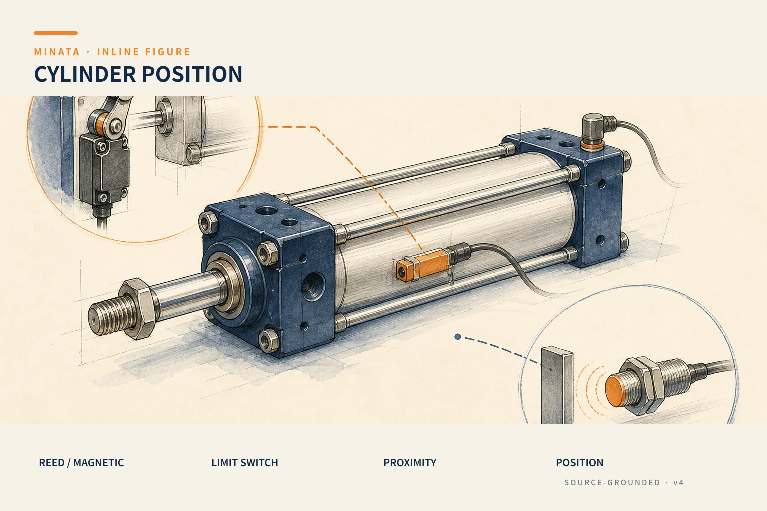
Before choosing: write the confirmation statement in mechanical language
A good signal must answer a specific operating question. "Clamp closed" can carry at least three meanings:
- The piston has reached the rod end. This is information internal to the cylinder; a magnetic sensor on the cylinder body reads exactly the object of interest.
- The clamp jaw has touched the workpiece. The piston may have reached the end, but the linkage is loose, the jaw is worn, or the workpiece is missing. If a later step needs force/contact confirmation, the piston signal is not enough evidence.
- The fixture assembly has reached an allowed position. A slide, crank or lever mechanism can turn the piston stroke into a different motion; the external position must be measured at that very mechanism.
In a sequence diagram, the signal names should also keep their exact meaning: CylinderA_Forward, ClampA_Touched and Slide_AtPosition are three different signals. Naming them clearly avoids a programmer treating a "forward" switch as evidence that the clamp is holding the workpiece safely.
When a magnetic sensor on the cylinder is the first choice
Most modern pneumatic cylinders have a magnetic piston and a groove for mounting a sensor. A magnetic sensor detects the magnet's field as the piston passes the sensor's location; this lets it read the position directly along the cylinder body without a cam, dog bar or separate actuating mechanism. It is the compact choice for the two ends of stroke, a mid-stroke position, or a repeatable stopping position when the cylinder itself is what needs monitoring.
The MISUMI catalog groups the switch/sensor mounting rails and brackets separately by cylinder body type. This detail matters: they are all "magnetic sensors," but a C-slot, a T-slot, an external band clamp or a holder for a round body cannot be interchanged just because the connector looks the same. Before ordering, cross-check the exact brand, cylinder series, body diameter and mounting-accessory code.
The practical advantages of this option include:
- No cam striking the sensor head, so no impact load is added to the mechanism.
- The sensor position can be shifted along the cylinder body to get an early-warning or mid-stroke point, within the limits of the groove length and the real stroke.
- The cable and sensor head sit close to the cylinder, keeping the mechanism compact where mounting space is limited.
- The signal suits basic interlocking: allow the next step only when the piston has returned or advanced.
However, a magnetic sensor only proves that the piston's magnet is at a position relative to the sensor head. It does not measure clamping force, does not prove the workpiece is present, and does not reliably detect that a coupling behind the cylinder rod has transmitted the full stroke. For a station with a risk of clamping without a workpiece or of mechanical jamming, add a workpiece sensor, a fixture-position sensor or pressure monitoring appropriate to the safety/quality requirement.
Choosing the magnetic sensor by cylinder body, electrics and wiring
Once the principle is chosen, ordering the part must follow a fixed order.
1. Confirm the piston has a magnet and a mounting groove
Do not infer that the piston has a magnet from seeing that the cylinder has a groove. Check the cylinder's catalog or order code: many series have magnet and non-magnet versions. If the piston has no magnet, mounting a sensor on the body will not produce a stable signal. If using an external clamp, check the diameter range, body material and cable direction to avoid the cable rubbing against a moving mechanism.
2. Choose the output type to match the machine's inputs
A cylinder sensor usually has a DC output of PNP or NPN type, and an NO/NC type depending on the model. The PLC input, relay interface or remote I/O decides how the load is wired. The same M8/M12 connector or the same three-wire cable does not guarantee that two sensors are interchangeable. Before buying, record in the BOM: supply voltage, number of wires, PNP/NPN, NO/NC, cable/connector type and the pinout of the receiving device.
3. Read the environmental specs as part of the mounting position
A position on the cylinder body often faces vibration, oil, wash-down water, chips and repeated cable flexing. The IP rating, cable bend radius, temperature range and vibration capacity must be read from the datasheet of the exact part. The IP rating is the enclosure-protection code per IEC 60529/JIS C 0920; it does not substitute for confirmation about cutting oil, cleaning chemicals or an over-tensioned cable.
4. Leave room for adjustment and anti-slip
During commissioning, put the piston at the real position that needs signaling, shift the sensor until the LED/PLC changes state, then tighten the holder to the manufacturer's torque. Then run many cycles at the actual working pressure. If the holder slips due to vibration, the signal will drift its trigger point over time; mark the position after acceptance and check it during periodic maintenance.
When a limit switch is more valuable than a magnetic sensor
A limit switch changes state when a mechanical part acts on a plunger, lever, roller lever or equivalent. It needs a mechanical actuating force and stroke, but in return it can be placed exactly where confirmation is needed: a guard has closed, a slide has touched a stop, a clamp mechanism has rotated past an angle, or a jaw has returned to a prescribed mechanical position.
It suits when:
- The cylinder has no magnetic piston, or replacing the cylinder should not be tied to a magnet model.
- You need to confirm the end mechanism, rather than just confirming the piston.
- The target to detect is non-metallic and there is no way to mount a photoelectric/proximity sensor.
- The detection point must withstand electromagnetic interference, or has a mechanical configuration where a reliable cam is already used.
In return, the mechanical design must be more careful. The cam must approach in the direction the manufacturer allows, have a lead-in section rather than striking the switch head directly, provide reasonable overtravel, and not use the switch body as an end-of-stroke stop. Check the release state too: does the return spring bring it back when the mechanism vibrates or when the cam is worn? For a high-speed position, the impact force and the switch's mechanical life become data that must be read in the catalog.
A common design mistake is mounting a limit switch right at the end of stroke and using it as a stop. When the air pushes the mechanism past the point, the roller or plunger takes the full impact energy; the signal may still work for a while, but the switching point and durability are no longer controlled. A mechanical stop, a shock absorber and a switch are three separate roles.
When an inductive proximity sensor fits better
An inductive proximity sensor detects a metal target without contact. The OMRON technical guide describes the family of proximity sensors by non-contact principles, including electromagnetic induction with eddy currents on a metal object; the document also distinguishes them from limit switches that need mechanical contact. For a cylinder, the common arrangement is to mount a metal dog/cam on the slide or fixture connected to the cylinder rod, then place the sensor at the position to be signaled.
This option is good when the position to confirm sits outside the cylinder body: for example a clamping table passing a position, an arm rotating to a final angle, or a slide that has actually returned home. Being non-contact, it avoids wear from an actuating cam and can perform well in an oily, dusty environment if the right housing/protection rating is chosen.
But "metal" is not enough to lock the part number. The nominal detection distance is usually stated with a standard target; the metal type, dog size, flush/non-flush mounting and metal blocks near the sensor face can all affect the switching point. Do not turn the nominal spec into a final mechanical coordinate. Build a dog with a large enough face, leave the mounting clearance per the datasheet, and re-test on the real metal assembly.
In a design with several sensors close together, also check the path of each dog. A shared metal target for two signals sometimes causes cross-triggering, especially when the fixture changes. Drawing the detection zone, the direction of motion and the name of each signal clearly on the assembly drawing helps verify the logic from the design stage.
Three selection maps for common situations
A cylinder pushing a workpiece onto a conveyor
If the PLC only needs to know the piston has advanced/returned to avoid issuing opposite commands at once, choosing two cylinder-fit magnetic sensors is the most compact. If you need to know the workpiece has actually left the magazine, add a workpiece-detection sensor at the exit position. The "piston advanced" and "workpiece has exited" signals do not substitute for each other.
A cylinder rotating a lever through 90°
A magnetic sensor is still useful to monitor the piston, but a proximity sensor placed near the crank arm, or a limit switch with a cam, can reflect the lever angle better. Choose proximity if there is a metal dog and you need to avoid contact; choose a limit switch if you need a mechanical actuation at a defined point. For a motion with inertia, check the position after the mechanism has settled, and do not take a signal mid-rotation as final evidence.
A clamp using a toggle cylinder
Two magnetic sensors indicate the piston closed/open. If quality depends on the workpiece being clamped in the right position, add a workpiece-presence sensor or an external switch/sensor on the fixture to confirm the jaw. If the requirement is a safety function for the operator, use a safety device and a safety-rated architecture assessed to the machine's requirements; do not take a general-purpose position sensor as the sole safety measure.
Easily overlooked: signal timing and pneumatic sequencing
How long before or after the mechanical motion the sensor signal arrives is part of the cycle design. A magnetic sensor on the body may signal before the piston hits the end cap, depending on the magnet position and the response zone. Proximity may signal before the dog reaches the final mechanical coordinate. A limit switch may signal when the cam first touches or after the full stroke is pressed. The PLC must use each signal by that exact meaning, combined with a reasonable timeout and error handling when opposing signals appear at once.
During commissioning, log at minimum these cases: loss of air, pressure drop, jammed workpiece, open sensor cable, loose holder and restart after an emergency stop. A well-chosen sensor placed wrongly in the sequence still creates hard-to-find faults: the machine waits for a signal that never comes, or runs the next step when the mechanism is not truly safe.
Ordering and on-site acceptance procedure
- Draw the position to be proven on the mechanical diagram, not just "sensor forward/back."
- Choose the principle: piston magnet → magnetic sensor; mechanical contact point → limit switch; metal dog → inductive proximity.
- Lock the exact cylinder model, groove/holder, voltage, output, connector and cable direction.
- For proximity/limit switch, design the dog or cam right in the drawing; do not leave it as a workshop improvisation.
- Mount and adjust at pressure, load, speed and temperature close to operating conditions.
- Check the signal on the PLC/HMI, including NO/NC logic, wire loss and both end-of-stroke signals.
- Store photos of the mounting position, the part number, the pinout and the replacement criteria in the machine file.
Common mistakes
- Using a magnetic sensor to assert the clamp is holding the workpiece. It only reads the piston magnet; add an appropriate signal if you need to prove the fixture/workpiece state.
- Ordering a sensor by the shape of the connector. You must check the correct groove, magnetic piston, output and pinout.
- Using a limit switch as a stop. The mechanical stop and shock absorber must take the load; the switch only senses.
- Using proximity with too small a dog, or changing the dog material after commissioning. Re-check per the datasheet and the real sample.
- Letting the cable sweep into the mechanism. The fault often appears after many cycles; clamp the cable, leave a bend radius and protect it at the moving point.
- Merging an operating signal with a safety function. The safety level must be assessed separately per the machine design and the applicable standard.
Quick selection checklist
- [ ] Does the signal need to confirm the piston, a mechanical contact point, or an external mechanism position?
- [ ] Does the cylinder have a magnetic piston and the correct groove/holder for a magnetic sensor?
- [ ] If using a limit switch, does the cam have the right actuation direction, overtravel and an independent mechanical stop?
- [ ] If using proximity, is the dog the right metal, size and mounting clearance per the datasheet?
- [ ] Do the PNP/NPN, NO/NC, voltage, connector and pinout match the PLC/remote I/O?
- [ ] Are the protection rating, oil/water, vibration, temperature and cable routing suited to the mounting position?
- [ ] Does the cycle distinguish "piston arrived" from "fixture/workpiece is in the right state"?
- [ ] Have you tested loss of air, jammed workpiece, open wire and timeout before handover?
If you are locking down a sensor for a cylinder assembly or a clamp fixture, MINATA can review the point to confirm, the mounting conditions and the I/O logic with you before the BOM. See MINATA's Engineering & Manufacturing service.
References
- MISUMI, FA Factory Automation 2018 — Sensors/Switches, sections on proximity sensors, position switches and mounting rails/brackets; the catalog is used to cross-check the mounting type and the specs that must be chosen by the exact part number.
- OMRON, Proximity Sensors Technical Guide — classification of non-contact proximity sensors, related to JIS C 8201-5-2/IEC 60947-5-2.
- IEC 60529 — the IP code system; check the datasheet of the specific model for the real environment.
More in the Device Selection series
View all MINATA technical articles