Device Selection #11: Flexible, Bellows, Oldham or Rigid Coupling — Choosing by Misalignment and Backlash
Short answer: choose a bellows coupling when a servo or encoder shaft needs low backlash, good torsional stiffness and even angular motion; choose an Oldham when two shafts have significant parallel misalignment to compensate; choose a flexible coupling when you need to absorb vibration, reduce shock and, depending on type, electrically insulate; choose a rigid coupling only when the two shafts are aligned very well concentrically and the structure can withstand the reaction force from misalignment. The nominal torque is only one line in the selection table. The shaft misalignment, rotational speed, inertia, backlash and shaft-mounting type are what decide how long the coupling survives.
Quick comparison
| Criterion | Flexible (jaw/elastomer) | Bellows | Oldham | Rigid |
|---|
| Backlash | Depends on construction and elastic element | Very low in the precision type | Possible per the sliding-disc construction | Very low if mounted correctly |
| Angular/shaft misalignment compensation | Yes within the catalog limits | Yes within the catalog limits | Strong for parallel misalignment | Almost none |
| Torsional stiffness | Medium to high | High | Usually lower than bellows | Very high |
| Vibration/shock absorption | Good | Less, biased toward accuracy | Has the sliding of the middle disc | Almost none |
| Typical use | Pump, general drive, stepper | Servo–ball screw, encoder, positioning | Motor and mechanism with parallel eccentricity | Two precisely machined/aligned shafts |
| Main risk | Elastic element ageing/overload | Excess misalignment, bending load | Disc wear, speed/load limit | Pushing a misalignment load into the bearings and shaft |
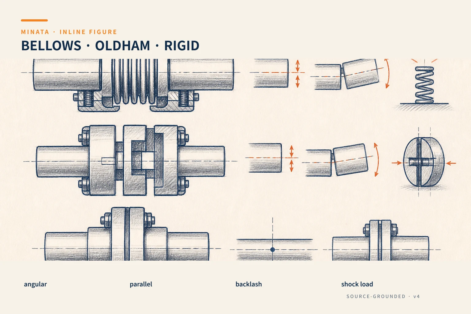
A coupling is not only to "join two shafts"
A coupling transmits torque from the motor to a ball screw, gearbox, encoder, pulley or other mechanism. At the same time, it must face the real misalignment between the two shaft centers: parallel offset, angular offset and axial displacement. Misalignment can come from machining tolerance, the mounting face, temperature, a machine frame deforming under load, or maintenance disassembly. If you choose a coupling too rigid for an unaligned system, the reaction force does not disappear; it becomes a load on the motor bearings, the ball-screw support bearings and the shaft.
Conversely, a coupling too soft or with large backlash can make a positioning system elastic. The motor encoder reports it reached the command while the table is still twisting or taking up clearance. This easily shows on reversal, load change, or when raising the servo gain. So choosing a coupling is a balancing problem: transmit enough torque, compensate the necessary misalignment, keep suitable stiffness/backlash and not create an extra load that destroys the mechanism.
MISUMI describes a flexible coupling as an element that can compensate lateral, angular and axial misalignment within each model's limits. The maker's selection guide also requires checking the torque, maximum speed, allowable misalignment and bore size — four things to be checked at once, not replaced by an identical bore size.
Measure and name the three misalignment types correctly
Parallel misalignment occurs when two shafts are parallel but their centers do not coincide. When rotating, some coupling types must bend or slide every revolution. An Oldham uses a middle disc sliding in two perpendicular slots, so it is usually chosen when a relatively large parallel misalignment must be accommodated. In return, checking the disc's wear, load, speed and backlash per the catalog is mandatory.
Angular misalignment is when two shafts intersect at a small angle. Bellows, disc couplings and some flexible couplings can compensate within limits, but the allowed capability does not mean you should mount right at the limit. The larger the misalignment, the higher the bending moment and cyclic load. Align well first, then let the coupling compensate the remaining error — that is the correct way.
Axial displacement occurs due to heat, position tolerance or the mounting mechanism. Many couplings have their own axial-motion limit. Ignored, a coupling can press into the bearings or pull the shaft with each thermal cycle. Read the angular, parallel/lateral and axial symbols of the exact model; these numbers cannot be interchanged.
Measure the misalignment after the whole frame, motor plate, rails and load are mounted close to the operating state. A dial gauge, a straightedge and a suitable alignment procedure help find the shaft center before putting the coupling in a state of "carrying" the assembly error. If the machine sees heat or has a long frame, assessing the misalignment at operating temperature or under load also matters.
Flexible coupling: controlled vibration and shock damping
A jaw/elastomer coupling usually has two hubs and an elastic element in the middle. The spider's material/hardness affects the torsional stiffness, vibration damping and how much shock is transmitted. Some designs create electrical insulation between the two sides. They suit general drives, stepper motors, small pumps, conveyors, mechanisms with moderate impact, or where you want to reduce shock transmitted into the motor.
The advantage does not mean exemption from alignment. The elastic element can heat, age, crack or wear under oil, chemical, heat and overload conditions. Checking the material, temperature, environment and replacement guidance is part of the BOM. If accurate position is a high criterion, check the backlash and torsional stiffness at the real load; two similar-looking models can give a noticeably different servo response.
A flexible coupling suits a load with shock or a need for vibration damping, but should not be used to mask large concentricity error. Large eccentricity still creates a cyclic load and wears the elastic element early. This is a common symptom: replacing the spider stops the vibration for a while, then it returns. The root cause may be at the motor mounting face or the rails, not the spider.
Bellows: prefer low backlash and even angular motion
A bellows coupling uses a thin corrugated metal tube between two hubs. This structure can give high torsional stiffness and very low backlash, while compensating some misalignment per the maker's specs. It is usually seen between a servo and ball screw, an encoder and measuring shaft, a precision rotary table, and axes that reverse a lot without wanting added backlash.
A bellows is not made to handle large misalignment. The corrugated tube must work elastically within limits; excess misalignment, bending load or poor hub mounting reduces life. Check the peak torque during acceleration, the axial load, the rotational speed and the moment of inertia. If the motor spins fast, the coupling's balance characteristic and allowed speed are real safety parameters, not just performance data.
In a servo axis, the coupling's torsional stiffness is part of the control loop. A coupling too soft creates a torsional lag between the motor encoder and the load, usually making tuning harder. A coupling too rigid with poor alignment throws the load into the bearings. You must look at the whole chain motor–coupling–ball screw/gearbox–load; #09 on choosing servo, stepper and induction explains why inertia and the motion profile must go with the motor.
Oldham: solving the parallel-misalignment problem
An Oldham coupling has two hubs with slots and a central disc that transmits torque through two perpendicular faces. When the two shaft centers are offset in parallel, the disc slides back and forth to compensate. So an Oldham usually suits a motor and a mechanism mounted on two faces that cannot yet be perfectly concentric, especially when the eccentricity reaction force is a problem. The MISUMI catalog notes an Oldham allows a large lateral misalignment and easier installation in that application group.
The sliding motion creates conditions to check: the disc material, lubricated or dry running by design, heat, speed, wear and backlash increasing over time. A zero backlash level should not be inferred from appearance; take the exact model's spec and the hub/disc configuration. For an encoder or very sensitive measurement, a bellows or a disc coupling may be a better option if the misalignment has been aligned small.
Do not use an Oldham just because the mounting faces produce too large a misalignment. If the misalignment exceeds the catalog, each revolution can put the disc through a large sliding stroke, heating and wearing quickly. Fix the mounting reference, add alignment capability, or reconsider the motor-mounting architecture before increasing the coupling size.
Rigid coupling: precise when the mounting condition is really precise
A rigid coupling is a hub joining two shafts directly, usually giving high torsional stiffness and almost no backlash. It is useful for tightly machined/aligned shafts, measuring fixtures, or two shaft parts on the same reference. But it hardly compensates misalignment at all. Any parallel/angular offset forces the two shafts to run on an unnatural path, transferring force into the bearings.
A thinking mistake is to use a rigid coupling because "a servo needs stiffness." A servo needs the correct stiffness and backlash per the requirement, and the motor bearings also need protecting. If the frame is welded, the plate face is thin or the temperature range is large, a rigid coupling easily turns the assembly error into vibration and bearing heat. Choose it only when you have the alignment data, the structure and the ability to keep concentricity after maintenance.
The selected torque must include the load mode
For servo/stepper, the MISUMI guidance recommends taking the compensating torque as the motor peak torque times the compensating factor of that very coupling line, then choosing a transmission capacity larger than the result. For a general power-transmission motor, the catalog uses the load torque and an application factor by load type. The practical meaning: do not just take the steady-running torque. Acceleration, reversal, jamming, shock from the mechanism and the number of starts/stops completely change the coupling's condition.
When you do not have the data to compute the full dynamic load, take the application factor published by the coupling maker for the drive type, load form and cycle. Do not set a factor "for safety" without recording the assumption. Besides torque, check the maximum speed, the bore, the clamp/set-screw/key type, the tool-access clearance for mounting and the disassembly capability in maintenance. A coupling with the correct bore but no space to tighten the screw will cause a fault right on the assembly floor.
Selection and installation sequence
- Define the two shafts. Diameter, tolerance, mounting length, key/keyway, clamp type, shoulder position and tightening space.
- Record the torque and speed. Include continuous running, acceleration peak, reversal, shock load and cycle.
- Measure the misalignment. Separate lateral, angular and axial; compare with the model's own limits, with a margin.
- Choose the dynamic characteristic. Positioning/encoder needs low backlash; a shock load needs damping; parallel offset needs an Oldham or an equivalent solution.
- Install per the documentation. Clean the shaft, leave an axial gap if the maker requires, tighten to the correct torque, use a suitable anti-loosening measure, and check by turning by hand before applying power.
- Confirm after running. Observe vibration, noise, hub/bearing heat, wear marks and screw position after the test cycle. Realign if needed; do not just fit a new coupling.
Common selection mistakes
- Choosing by bore and torque only. Ignoring lateral/angular/axial misalignment makes the coupling carry the assembly error.
- Choosing a rigid coupling for a frame whose concentricity is unchecked. The motor bearings and ball screw bear the consequences first.
- Using a soft coupling to mask a large error. It may reduce the symptom, not remove the cause.
- Dropping the servo's peak torque. The coupling fails during acceleration even though the steady-running torque is very low.
- Forgetting the environment. Oil, heat, chemicals and dust act directly on the spider or the sliding disc.
Quick selection checklist
- [ ] Have you recorded the continuous torque, peak torque, speed and number of reversals?
- [ ] Have you measured parallel, angular and axial misalignment separately in the real mounted state?
- [ ] Does the positioning/encoder axis need very low backlash? Yes → consider a bellows or disc coupling per spec.
- [ ] Is parallel misalignment a prominent constraint? Yes → consider an Oldham within the catalog range.
- [ ] Do you need vibration absorption or shock load? Yes → consider a flexible coupling with a suitable element material.
- [ ] Use a rigid coupling only when concentricity, structure and bearing load are verified?
MINATA can review the chain motor–coupling–ball screw/gearbox, check the mounting misalignment and choose a configuration that can be machined, installed and maintained. Talk to the Engineering & Manufacturing team.
References
View all MINATA technical articles