Device Selection #09: Servo, Stepper or Induction Motor — Choosing by Motion and Feedback Level
Short answer: use a servo for an axis that must follow position or speed under a changing load, needs high acceleration and needs to detect deviation; use a stepper for stepped motion, a short stroke or a simple cycle when the load is controlled; use an induction motor for a continuously rotating mechanism that needs durability, stable running and does not require servo-level axis positioning. All three can spin the same pulley or ball screw, but the way they receive commands, feed back and handle overload differs. The decision must start from the load's motion, then move to the power rating printed on the motor.
Quick comparison
| Criterion | Servo | Stepper | Induction (asynchronous) |
|---|
| Feedback | Encoder and driver closed-loop | Usually open-loop; closed-loop stepper versions exist | Usually by speed; can use an inverter and auxiliary feedback |
| Main strength | Following position/speed, accel/decel, tracking-error alarm | Simple position division, good torque at low speed | Continuous rotation, durable, common for pumps/fans/conveyors |
| Control | Servo driver, tuning and position/speed signal | Pulse-generating driver or closed-loop control | Direct start, contactor or inverter |
| When the load changes | Suitable if correctly sized and tuned | Needs a margin to avoid losing steps | Suits rotating loads, speed adjusted by the inverter |
| Point to watch | Load inertia, tuning, encoder cable, holding brake | Step loss, resonance, torque falling with speed | Starting, slip, braking, positioning capability |
| Typical example | Robot, rotary table, positioning ball screw | Small slide, feeding, adjusting mechanism | Fan, pump, mixer, conveyor |
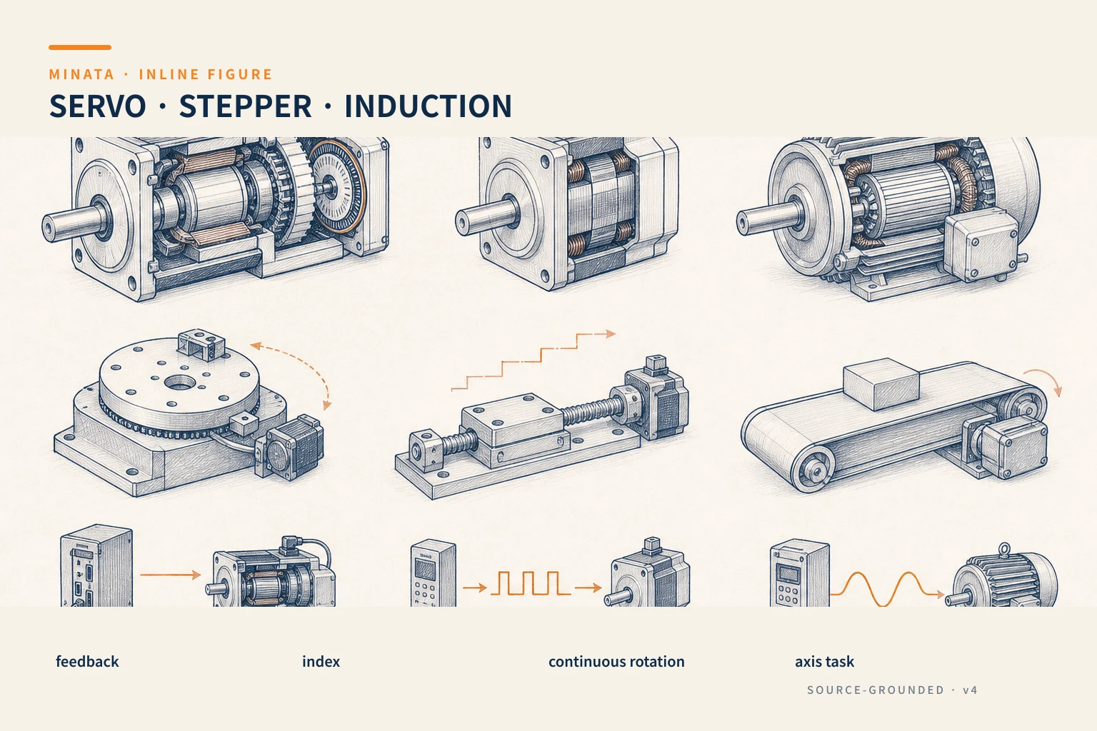
Do not start with the question "how many watts?"
A motor is just one link. The load at the other end may be a slide, a winding drum, a conveyor, a rotary table, a pump or a lifting mechanism. Each load type produces a different torque when running steadily, accelerating, reversing and stopping. So the first question should be: does the axis need to know where it has reached, or only to rotate? If the answer is "it must know and must correct when it drifts," a servo system has a clear advantage because the encoder measures the real motion and the driver compares it with the command.
Next, break the task into four data streams: the load mass or torque; the speed and cycle time; the stroke or rotation angle; the requirement on fault or power loss. These are the inputs to compute the mechanics, choose the transmission and choose the motor. Reading each power label and replacing with a bigger motor usually leaves two risks: the motor still cannot keep up with the inertia during acceleration, or an oversized motor makes the system costly, hard to tune and unable to use its full working range.
Servo: choose when a position error is a signal to handle
A servo consists of a motor, an encoder and a driver. The encoder sends position/speed to the driver; the driver adjusts the current fed to the motor to follow the command. This structure is useful when the load changes, when the axis must reverse repeatedly, or when the machine must stop at a controlled position. If the mechanism jams, the belt slips, there is a collision or it does not follow the command, the driver can detect it through a deviation limit and send an alarm signal to the PLC. This very ability to observe deviation distinguishes a servo from ordinary open-loop pulse generation.
A servo suits a ball screw, rotary table, robot axis, a gripper head with a motion profile, a packaging machine that changes many formats, and an axis synchronized with another axis. When the requirement is only "go to a limit switch and return," a servo still works, but the cost of the driver, encoder, cable and setup time may not be justified. Choose it when flexibility and feedback information have a clear value for the machine.
When reading a servo catalog, separate continuous torque from peak torque. Continuous torque relates to heat during long running; peak torque is for the acceleration phase, reversal or resisting a short-term resisting force. A cycle may use little average torque but need a high peak when lifting the load. The torque-speed curve of the chosen motor/driver set is the final check, because the available torque also depends on the supply and the driver.
Another important check is the inertia reflected to the motor shaft. The ball screw, pulley, gearbox and translating load all contribute to the inertia the motor sees. A system with load inertia too large relative to the motor can vibrate, respond slowly or need more cautious tuning. A gearbox changes the reflected inertia; so compute the motor–gearbox–load as one chain. See how to choose the transmission in #03 on ball screw, timing belt and rack and pinion and #04 on gearboxes.
Stepper: compact for known position-division commands
A stepper motor rotates in electrical steps; the driver receives pulses and creates current for the phases. This control method is easy to pair with a pulse generator, a PLC or a simple motion controller. For a task with a short stroke, a stable load and a moderate speed, a stepper makes a compact solution for an adjusting table, a feeding mechanism, a metering valve, a screwdriver head or a position-dividing rotary axis.
What must be understood is that the number of pulses sent does not by itself prove the axis reached the position. If the load torque exceeds the motor torque at that speed, if the acceleration is too harsh, or if the mechanism resonates, the motor can lose steps. An open-loop system keeps sending pulses while the real axis has already drifted. A home switch, a confirmation sensor, an acceleration limit and a torque margin are the design guardrails to have. For a machine that must know a position error within the cycle, choosing a closed-loop stepper or a servo is safer.
Do not read the holding torque on the label as the available torque at running speed. A stepper's torque changes with speed, driver voltage, current setting and load condition. Always take the torque-speed curve of the exact motor/driver, then place the operating point in a zone with a margin left. If the mechanism makes a vibrating noise in a speed zone, review the microstepping, acceleration profile, mechanical stiffness and coupling type; simply raising the current does not necessarily solve the root cause.
A closed-loop stepper is a middle option worth considering. It adds an encoder and correction logic to track position, while keeping operation close to a stepper in many applications. It does not replace a servo in every case; compare the load curve, speed, control type and fault-alarm requirement rather than inferring from the technology name. Oriental Motor also notes that a servo usually has the advantage at higher speed and higher load inertia, while a stepper usually suits short, fast motions if the load conditions are suitable.
Induction: works well for continuous-rotation tasks
An induction motor, usually called an AC asynchronous motor, appears very often in fans, pumps, conveyors, mixers, blowers and continuously rotating power mechanisms. The rotor needs no brushes; the construction is familiar, durable and easy to source replacements for. When you only need run/stop or a speed change within a working range, a contactor combined with motor protection, or an inverter, usually makes a reasonable control system.
An induction motor has no default encoder to perform precise positioning like a servo. An inverter can control speed and has advanced control modes, but the requirement of a positioning axis must still be assessed separately: stopping accuracy, changing load, braking, feedback and how position is confirmed. For a conveyor that must run continuously at several speeds, this is usually enough. For a rotary table that must stop at the exact angle, a servo system or a motor with an encoder/motion control may be simpler at the whole-system level.
With an induction motor, look closely at the load's starting mode and starting torque. Fans and pumps have a different characteristic from a load-carrying conveyor, a screw conveyor or a crusher. An inverter helps create an accel/decel ramp and limit current, but must be chosen together with the motor, voltage, installation conditions, cabling and load. If the load has large inertia or the shaft can drive the motor when braking, discuss the braking approach clearly with the supplier: free stop, decel braking through the inverter, a braking resistor or regeneration each create different requirements.
The selection process by the real motion
- Describe the load at the output. Record the mass, radius, resisting force, direction of motion, friction and load varying over time. For a lifting mechanism, clearly separate the payload from the gravity force.
- Draw the profile. Record the speed, acceleration, run time, rest time, number of reversals and daily cycle. This is the basis for a thermal check, not just the time of a single trial run.
- Determine the feedback level. Do you only need to send commands, need a sensor to confirm the end of stroke, or need to know the deviation continuously? This question narrows the choice fastest.
- Choose the transmission. A ball screw, belt, rack and pinion, gearbox or winding drum reflects force/speed to the motor differently.
- Read the curve of the whole set. For a servo, the motor and driver; for a stepper, the motor and driver; for induction, the motor and the starting method/inverter.
- Check for faults. Power loss, mechanical jam, belt break, overtravel and a dropping load need an independent safety mechanism where necessary.
Three easy-to-decide situations
A slide mounting components that changes model often. It needs to change position, speed and acceleration in software, and detect the axis not following the command. A servo with a ball screw/timing belt and a home sensor is the suitable configuration. If the load hangs vertically, add a holding-brake assessment per #12 on brakes and clutches.
A label-feeding mechanism rotating a fixed angle, light load and stable cycle. A stepper can be the economical choice if the torque curve at the working speed has a margin, the mechanism does not jam, and there is a home to restore the reference. Do not drop the sensor just because the motor receives enough pulses.
A conveyor moving boxes at a few speeds. An induction motor combined with a gearbox and an inverter is usually practical. The requirement to confirm is the starting torque at full load, the braking method, the conveyor type and the environmental conditions; positioning each box can be left to a sensor and a stopper.
Common motor-selection mistakes
- Choosing a servo by nominal power and ignoring peak torque. The axis runs unloaded but alarms during acceleration or reversal.
- Using an open-loop stepper for an axis not allowed to lose position. One small jam can throw off the reference for the entire chain afterward.
- Assessing an induction motor as a positioning axis just because an inverter is fitted. A good speed-control inverter does not by itself create position confirmation at the load.
- Forgetting inertia and mechanical backlash. The right motor still gives poor results if the coupling, gearbox, belt or guide rail is unsuitable.
- Not recording the power-loss condition. A stopped motor does not mean a hanging load is held safely; a holding brake and an anti-drop mechanism must be considered separately.
Quick selection checklist
- [ ] Have you written the axis's speed, acceleration, cycle and number-of-reversals profile?
- [ ] Does the axis need position/speed deviation feedback while running? Yes → prefer a servo or closed-loop stepper.
- [ ] Light load, simple stroke/motion, has a home and a torque margin? Yes → consider a stepper.
- [ ] Continuous-rotation task, no need for precise axis positioning? Yes → consider an induction motor with a suitable speed-control approach.
- [ ] Have you checked the torque-speed curve of the exact motor/driver or motor/inverter set?
- [ ] Have you computed the load, inertia, transmission and braking/power-loss condition?
If the load and profile data are not clear yet, MINATA can help the machine team turn the task into parameters for choosing the motor, driver, gearbox and holding brake before ordering. Talk to the Engineering & Manufacturing team.
References
View all MINATA technical articles