Device Selection #15: Pin-and-Hole, Support Face or Jig — Choosing by Datum and Loadability
Short answer: use a pin-and-hole when you need to repeat a position from clear datums; use a support face/rest to establish a reference plane and take the reaction force; use a jig when you need to combine the rest face, pins, clamps and the loading action into a repeatable process. For a workpiece with two holes, the common approach is one round pin as the primary datum and one diamond pin as the secondary datum to avoid over-constraint. Adding two round pins into two tolerance holes does not make the fixture "more solid"; it can make the workpiece hard to insert, scratch the hole or deform under clamping.
Quick comparison
| Solution | Main role | When suitable | What to check |
|---|
| Round pin–hole | Defines the primary datum position in two directions | A clear datum hole, position must repeat | Pin/hole fit, lead-in, hardness, wear |
| Diamond pin–hole | Locks one direction, releases the error in the other | Two holes, repeated load/unload | Diamond-face orientation, hole-spacing tolerance |
| Support face/rest | Establishes the plane/height, takes the reaction | A datum face, workpiece needs support | Flatness, burr, number of rest points, access |
| Complete jig | Repeats locating + clamping + guiding | High volume/repeatability | 3-2-1 datum, ergonomics, error-proofing, maintenance |
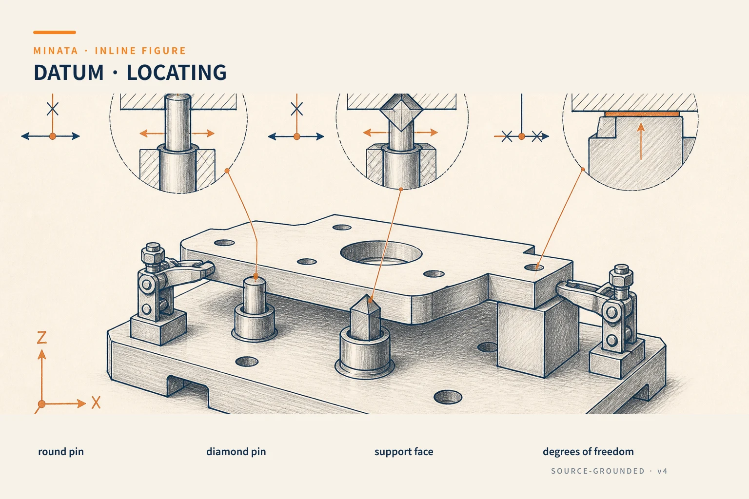
Locating must answer "which degrees of freedom to lock?"
A solid part has six degrees of freedom: three translations and three rotations. A fixture does not need to hold everything with clamping force. Rest faces and pins are used to constrain the necessary degrees of freedom; the clamp only presses the workpiece against those datums. The 3-2-1 principle is a common way of thinking: three points create the primary reference plane, two points set the second orientation, one point stops the remaining direction. Depending on the shape, pins/holes can take on part of that task.
First read the drawing: which datum relates to a critical dimension/function? On which face is the workpiece machined, with which part is it assembled, or where is it measured? If you choose the fixture datum by the easiest face to clamp but the product is inspected by two holes, the fixturing error transfers into the dimension being checked. A locating pin is only good when it grips the datum suited to the operation's goal.
Round pin and diamond pin: handling the tolerance of two holes
A round pin entering a hole defines the center in two directions on the plane. If you add a second round pin into a second hole, the exact distance between the two holes on the workpiece must match absolutely the distance between the two pins. In production, every part and every fixture has a tolerance. MISUMI recommends using one round pin and one diamond pin; this configuration allows easier insertion and compensates for a small deviation in the two-hole spacing, while avoiding over-location.
A diamond pin is not a "weaker" pin. It has two working faces in one direction and reduces obstruction in the perpendicular direction, so it still orients the workpiece but yields to the pitch error. The rotation direction of the diamond part must be drawn clearly: it must release along the direction of the two-hole spacing tolerance, and must not rotate arbitrarily after installation. If the workpiece has a slot, you can use a round pin in the primary datum hole and a slot/secondary pin for clocking by design.
Choosing the pin diameter must consider the hole tolerance, coating, burr, heat and the number of insertions. Too tight a pin makes the operator force it; too small a pin lets the workpiece rock. MISUMI has many pin-head types: taper, spherical, chamfer, small head, shoulder and bushing. A larger lead-in head helps insert the workpiece more easily during repeated handling; but the pilot part and the rest face are still where accuracy is checked.
Support face: the datum often underrated
A pin does not replace a rest face. If the workpiece sits on a face, you need enough rest points to create a plane and not make the workpiece rock. Three rest points establish a plane; a fourth rest point can be useful when there is an adjustment or the workpiece sags easily, but if all are fixed and the workpiece face is not flat, it can create an internal load. An adjustable support pin helps support a weak area after the workpiece has rested on the primary datum; it must not be used to push the workpiece off the reference.
The support face, stopper and rest face must be checked for burrs, machining chips and cleanability. A small burr on a datum face can create a deviation larger than the pin's tolerance. Design in relief, chip-clearing grooves, a replaceable surface or a hard insert for long-term use. When the workpiece is a thin sheet, avoid placing the clamping force so it sags between the rest points; place the support near where the clamping/machining force passes through.
When do you need a jig instead of loose pins?
A jig is a system of a body, datums, pins, supports, clamps and sometimes tool-guiding bushings. It is worth the investment when the operation needs many repeats, different people perform it, the fixturing time affects the cycle, or a wrong-fit error causes scrap. A good jig reduces the number of decisions the operator must remember: the part can only go in the correct orientation, rests on the correct face, clamps at the correct position, and gives feedback if the workpiece is missing.
Low volume or a prototype can use a stop block, removable pins and a simple screw clamp for adjustability. High volume needs consideration of replaceable pins/bushings, quick release, poka-yoke, a chip-clearing mechanism and the rest-face life. Do not turn the first jig into an overly complex block; lock the datum and the handling behavior first, then add features that serve productivity.
Fit and tolerance: locating is not clamping
An accurate pin needs a corresponding hole and bushing. Determine which part needs replacing when worn: many jigs use a replaceable bushing to protect the body. If the pin is pressed/removable, check the mounting method and the material hardness; if it is threaded, check the anti-rotation and the shoulder. Do not change the fit type just because the nominal diameter is the same.
The product tolerance must be allocated from the function. The article on IT7–IT9 tolerances is a cross-link for the cost and machinability part. For a fixture, state clearly the tolerance of the pin, bushing, datum face and center distance; a "high accuracy" requirement that cannot be machined/inspected will not create good locating.
The quick selection process
- Choose the datum by function/product, not by the easiest face to clamp.
- List the six degrees of freedom to constrain at the operation.
- Choose the primary rest face, the orientation points and the stop point; determine where the clamping force presses to.
- If there are two datum holes, prefer a primary round pin + a secondary diamond pin along the pitch-error direction.
- Choose the pin head, material, bushing, clearance and relief by the workpiece/number of insertions.
- Test with the worst-tolerance workpiece, a representative burr and the real user handling.
Common mistakes
- Using two round pins for two holes with a spacing tolerance.
- Using the clamp to pull the workpiece to the reference instead of letting it rest on the datum first.
- Ignoring burrs, chips and an easily worn rest face.
- Making the adjustable support the primary datum, deforming the workpiece when tightening.
- Designing an accurate pin with no way to replace it after wear.
Validate the fixture with a repeatability test
After assembling the jig, test with several representative workpieces rather than one nicest part. Load/unload repeatedly, measure the datum or the operation dimension, observe the force to insert the workpiece onto the pins, and check the contact surface. If the operator must rock the workpiece to insert it, if the workpiece only goes in when loosening the clamp, or if the contact mark sits on only one support, the jig geometry needs fixing before release.
Cast, stamped, welded and plastic parts have a different variability from CNC parts. Choosing a datum on a rough/deformed surface can turn an accurate locating pin into an error-creating point. Determine the variability the fixture allows, use a suitable rest face or support, and clearly distinguish a position used for locating from one used only for support.
At an operation with quality inspection, consider how to detect a wrong fit: a presence sensor, a retractable pin, a no-go gauge, a workpiece code or a mechanism that only lets the workpiece in one orientation. This is the handling-finishing part of the jig, after the datum principle is correct.
Material, surface and pin life
A pin subject to repeated insertion must have its material, hardness and surface considered by the workpiece. An aluminum workpiece can stick/gall on some surfaces; a workpiece with oil, abrasive particles or heat needs a different protection solution. Do not use a coating or material as a general statement: take the choice from the catalog, the environment and testing with the exact workpiece. For a bushing, prefer a replaceable part so you do not have to re-machine the jig body when the working diameter wears.
The pin head also affects handling. A taper or spherical lead-in helps insert the workpiece, but the accurate locating part must have enough engagement length and not touch the burr zone. If the workpiece is thin, design the pin-head/shoulder rest face so the clamping force does not concentrate on the hole edge. If a robot loads the workpiece, add lead-in and tolerance for the robot's error but still check for a collision in the worst-case state.
Handing the jig over to production
The jig drawing must record the datum face, the pin/bushing code, the diamond-pin orientation, the support height, the clamp position, the tightening force/condition when relevant, and the elements needing periodic inspection. The operating instructions should illustrate the order of loading the workpiece, confirming it rests on the datum, clamping, releasing and removing the workpiece. A short checklist at the station helps the fixture keep producing repeatability after a shift change or a personnel change.
When changing model, do not take an old jig and re-machine the pins without reviewing the new model's datums. The new hole may have a different tolerance, surface, force direction or measurement requirement; that makes the round-pin–diamond-pin principle and the support layout need changing.
That is a review step to have before re-releasing, even when changing just one hole or one datum face.
Quick selection checklist
- [ ] Have you defined the functional datum and the degrees of freedom to constrain?
- [ ] Does the workpiece have two locating holes? Yes → consider one round pin + one diamond pin along the pitch direction.
- [ ] Do you have three rest points/faces establishing the primary datum and the clamping-force path pressing to the datum?
- [ ] Have you checked the pin–hole fit, lead-in head, burr, bushing and number of load/unload cycles?
- [ ] Does the jig need poka-yoke, pin/bushing replacement and chip clearing for long-term operation?
MINATA can help define the datum, the locating principle and the jig's machinability before locking the manufacturing drawing. Talk to the Engineering & Manufacturing team.
References
View all MINATA technical articles