Manufacturing Engineering #05: How the Tolerance You Write Decides the Machining Cost — From IT7 to IT9
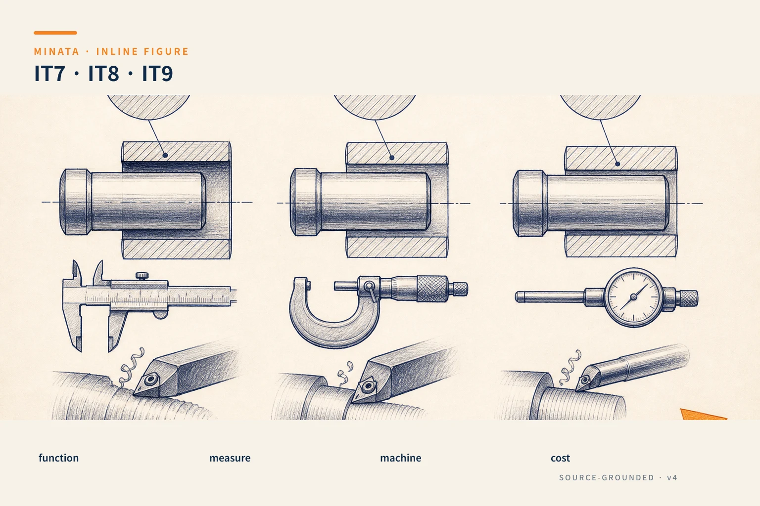
Short answer: each tolerance grade you tighten is a cost grade, because it forces the shop to change the machining method, add operations and add inspection. A dimension left at IT9 (a tolerance band of ~0.052 mm at the 18–30 mm size) is milled in one pass; forcing it down to IT7 (~0.021 mm) may require grinding or reaming; below IT6 requires fine grinding or wire cutting. (Note: the IT grade specifies the total tolerance band, not a ± value — look up the specific number by the size range, see the table below.) The cheapest way to reduce the machining cost is to state a tight tolerance only on the exact functional dimensions, and leave the rest as a general tolerance — this reduces the price far better than haggling with the shop. This article explains the IT tolerance-grade system, how it maps to machining methods and cost, and how to write the drawing to avoid overpaying.
Table mapping tolerance grade to method and cost
The table below uses the tolerance band for the 18–30 mm size as an example (standard IT values per ISO 286 / JIS B 0401):
| IT grade | Tolerance band (18–30 mm) | Method to achieve | Relative cost | Example application |
|---|
| IT6 | 0.013 mm (13 µm) | Grinding, fine reaming, fine wire cutting | Very high | Precise bearing-mounting hole, locating pin |
| IT7 | 0.021 mm (21 µm) | Reaming, grinding, careful fine turning/milling | High | Bearing-mounting hole, precise mating face |
| IT8 | 0.033 mm (33 µm) | Fine turning/milling | Medium | Ordinary mating face |
| IT9 | 0.052 mm (52 µm) | Milling/turning in one pass | Low | A non-tight fit dimension |
| IT10–IT11 | 0.084–0.130 mm | Rough machining, sheet cutting | Very low | Free dimensions, clearances |
Because the tolerance band of the same IT grade changes with the size, the following table gives the band (µm) at a few common size ranges (ISO 286 / JIS B 0401):
| Size range (mm) | IT6 | IT7 | IT8 | IT9 |
|---|
| 3–6 | 8 | 12 | 18 | 30 |
| 6–10 | 9 | 15 | 22 | 36 |
| 10–18 | 11 | 18 | 27 | 43 |
| 18–30 | 13 | 21 | 33 | 52 |
| 30–50 | 16 | 25 | 39 | 62 |
| 50–80 | 19 | 30 | 46 | 74 |
| 80–120 | 22 | 35 | 54 | 87 |
Unit: µm (0.001 mm). Source: ISO 286 / JIS B 0401; cross-checked with the MISUMI catalog technical tables.
What is the IT tolerance grade
The standard tolerance system (ISO 286, equivalent to JIS) divides accuracy into grades called IT (International Tolerance grade): IT01, IT0, IT1... up to IT18. The smaller the number, the tighter the tolerance. In ordinary machining, the common range is IT6 to IT11.
An important point: the tolerance of an IT grade depends on the size. At the same IT7, a 10 mm hole has a different tolerance from a 100 mm hole — the larger the size, the wider the absolute tolerance. So saying "IT7" is saying the relative difficulty, while the specific millimeter number must be looked up by the size range. This also means: a large part keeping a small absolute tolerance is much more expensive than a small part with the same number, because in IT terms it is far tighter.
Why each tighter grade costs more
The cost does not rise linearly but in steps, because at a threshold the current machining method cannot achieve it and you must switch to a more expensive method:
- Change the method. Fine milling reaches IT8 easily. To reach a stable IT7 on a hole, you usually add a reaming or grinding operation — more tools, more setups, more time.
- More machine time. Achieving a tight tolerance needs light cutting many times (more finishing passes), slower speed, more in-process measurement.
- More inspection. A dimension at IT7 and below usually must be measured with precise equipment (micrometer, dial gauge, coordinate measuring machine CMM) and a inspection record written. An IT10 dimension only needs calipers.
- Higher scrap. The tighter the tolerance, the higher the rate of parts falling outside the band, raising the unit price.
- Heat and distortion control. At a high accuracy grade, thermal expansion during machining and clamping distortion start to matter, requiring shop-temperature control and clamping care — a hidden but real cost.
Choosing which tolerance: follow function, not feeling
The core principle: tighten only where the function needs it tight. Ask each dimension one by one: "if this dimension varies within a wider range, does the part still fit and run correctly?" If yes, leave a wide tolerance.
Dimensions that usually really need to be tight:
- A bearing- or bushing-mounting hole: decides the runout and bearing life → usually H7.
- A locating pin and hole: decides the assembly position → H7/g6 or equivalent.
- A sealing contact face, a sliding face: needs good flatness and roughness.
- A dimension in a multi-part assembly chain (stack-up): accumulated error.
Dimensions that usually do NOT need to be tight:
- An outer envelope dimension that mates with nothing.
- A distance to an edge, the position of a clearance bolt hole (the hole already has clearance).
- The thickness, height of a non-contact part.
For the group that does not need to be tight, do not state an individual tolerance — leave them to the general tolerance declared once in the drawing corner (e.g. JIS B 0405 medium class, or ISO 2768-m). This both keeps the drawing tidy and tells the shop that most dimensions do not need an investment in accuracy.
Tolerance and fit: reading the H7/g6 symbol
On Japanese and international drawings, a fit tolerance is usually written with a letter + number symbol like H7, g6, k6. An upper-case letter is the hole, a lower-case letter is the shaft; the number is the IT grade. The letter position decides the fit type:
- Clearance fit: always has a gap, e.g. H7/g6 — a rotating shaft, free sliding.
- Transition fit: may be clearance or slightly tight, e.g. H7/k6 — precise location, removable.
- Interference fit: always tight, must be pressed, e.g. H7/p6 — fixed, not removed regularly.
Understanding the fit type helps you state the actual need: a shaft that must rotate smoothly in a bushing gets a clearance fit, do not state tighter than needed. Stating the wrong fit type both costs money and ruins the function (an interference fit where rotation is needed will seize).
Example: a drawing that overprices itself
A base plate 200 × 150 mm has 20 dimensions. The designer states ±0.01 mm on all 20 "to be safe." In reality only 4 dimensions are bearing-mounting holes and locating pins needing ±0.01; the other 16 are the outer envelope and clearance bolt holes, which run correctly at ±0.1 mm.
The consequence of the "to be safe" drawing: the shop must finish-machine and measure all 20 dimensions at high accuracy, and the price can be 2–3 times higher. If separated correctly — 4 dimensions H7, 16 dimensions per the general tolerance — the part works exactly the same but the price drops sharply. This is a classic example: the cost is not in the part, it is in how the tolerance is written.
There is a hidden cost few people notice: each dimension with a tight tolerance also drives the measurement and record-keeping cost. For a part delivered to a Japanese customer, the important dimensions usually must be measured on a CMM and come with an inspection record (検査成績書). Measuring one H7 dimension on a CMM and writing the record takes many times longer than a free dimension measured with calipers. The more tight dimensions, the longer the inspection record, the longer the delivery time. So reducing the number of tight dimensions not only lowers the machining cost but also shortens the inspection and delivery time.
When should you accept paying for a tight-tolerance cost? When that dimension really decides the function: a bearing hole decides the life and noise, a locating pin decides the assembly accuracy, a sliding face decides the wear. Here, saving on tolerance is saving in the wrong place — a cheap part with a failed function is far more expensive. The skill to develop is distinguishing which is a functional dimension worth investing in and which is a free dimension to let go.
Dimensional tolerance is not enough: there is geometric tolerance too
Many parts are correct on every dimension but still do not fit, because they lack constraints on geometry — flatness, parallelism, perpendicularity, concentricity, hole position. This is the GD&T (Geometric Dimensioning and Tolerancing) part, which Japanese drawings usually write with a symbol frame referencing a datum.
An easy example: a plate with four holes of correct diameter and correct relative spacing, but the whole four-hole group is offset from the reference edge by 0.3 mm. If the drawing only states the spacing between holes without stating the position relative to the datum, the part is still "acceptable" by dimension but does not mate with the counterpart. Stating a position tolerance relative to the datum blocks this error.
Geometric tolerance also drives cost: requiring high flatness on a large face forces surface grinding; requiring tight parallelism between two faces forces careful clamping and machining. So the "tighten only where functional" principle applies to geometric tolerance too — state flatness and parallelism only on the faces that need it, do not scatter it across the drawing. The set of geometric-tolerance symbols (straightness, flatness, roundness, cylindricity, parallelism, perpendicularity, angularity, position, concentricity, symmetry, runout) is per JIS B 0021.
The tolerance stack-up
When many parts assemble in series, the error of each part adds into the total error of the assembly. A five-part assembly, each part ±0.1 mm, in the worst case can be off by a total of ±0.5 mm — enough for the assembly not to work. This is why sometimes you must tighten a part's tolerance because it is in a stack-up chain, even though the part alone does not demand it.
The smart way to handle it: instead of tightening everything evenly, analyze the tolerance chain to find which dimension contributes most to the total error, then tighten only those. Or redesign to reduce the number of links in the chain (fewer parts in series, use one common locating part). Reducing the stack-up is usually much cheaper than tightening each link.
Tolerance and surface roughness go together
Dimensional tolerance and surface roughness (Ra) are two different but related requirements. A tight-fit face or a sliding face needs both a good dimensional tolerance and a fine enough surface; stating a tight tolerance while forgetting the roughness may leave the face rough and quick to wear. Conversely, stating too fine an Ra (e.g. Ra 0.2 µm) for a non-contact face is a waste — each finer roughness grade is also an added cost like tolerance. The principle is still: state the roughness by the surface's function, mating and sliding faces need to be fine, free faces can be left at the rough-machining finish.
Common mistakes
- Stating a uniformly tight tolerance "to be safe." It overprices without adding function.
- Not declaring a general tolerance. The shop must ask back or guess, easily wrong and slow.
- Stating too tight an IT for a large part. At the same IT grade, a large part is much more expensive; consider carefully.
- Confusing the fit type. Stating an interference fit where rotation is needed, or a clearance fit where location is needed.
- Ignoring geometric tolerance (flatness, parallelism, position). Sometimes the function depends on these more than the dimensional tolerance; if omitted, a dimensionally correct part still does not fit.
Tolerance-writing checklist
- [ ] Have you asked each dimension "if it varies wider, does it still run correctly"?
- [ ] Have you declared a general tolerance (JIS B 0405 / ISO 2768) in the drawing corner?
- [ ] Do only the functional dimensions get an individual tight tolerance?
- [ ] Have you used the correct fit-type symbol (H7/g6...) by the rotation/location/press need?
- [ ] For a large part, have you considered the absolute tolerance rather than mechanically following the IT grade?
- [ ] Have you considered geometric tolerance (flatness, position) if the function needs it?
To optimize a drawing to reduce the machining cost while keeping the correct function, MINATA can review the tolerances on the drawing and suggest where to loosen and where to keep. See MINATA's Engineering & Manufacturing service.
More in the Manufacturing Engineering series
View all MINATA technical articles