Device Selection #17: 2, 3 or 5-Port Solenoid Valve — Choosing by Circuit and Safe State
Short answer: choose a 2/2 valve to open/close one air line; choose a 3/2 valve for a single-acting cylinder or an air signal that needs supply–exhaust through one working port; choose a 5/2 valve for a double-acting cylinder that needs to reverse advance/retract; choose a 5/3 valve when the spool's center position must create a defined behavior when neither coil is energized. Before choosing the coil voltage, thread or manifold, draw the supply line, the working line, the exhaust line and answer what the mechanism must do on power loss.
Quick comparison
| Valve type | Typical ports/positions | Used for | Deciding question |
|---|
| 2/2 | 2 ports, open/close | Supply/block air, blow, auxiliary valve | Normally open or closed? Is the flow enough? |
| 3/2 | Supply–working–exhaust | Single-acting cylinder, pilot, signal | When the coil releases, is the working port supplied or exhausted? |
| 5/2 | Supply, 2 working, 2 exhaust | Double-acting cylinder | Use single/double solenoid? What is the released state? |
| 5/3 | Like 5/2, with a center position | Axis needing a specific center behavior | Is the center closed, exhaust or pressure right for machine safety? |
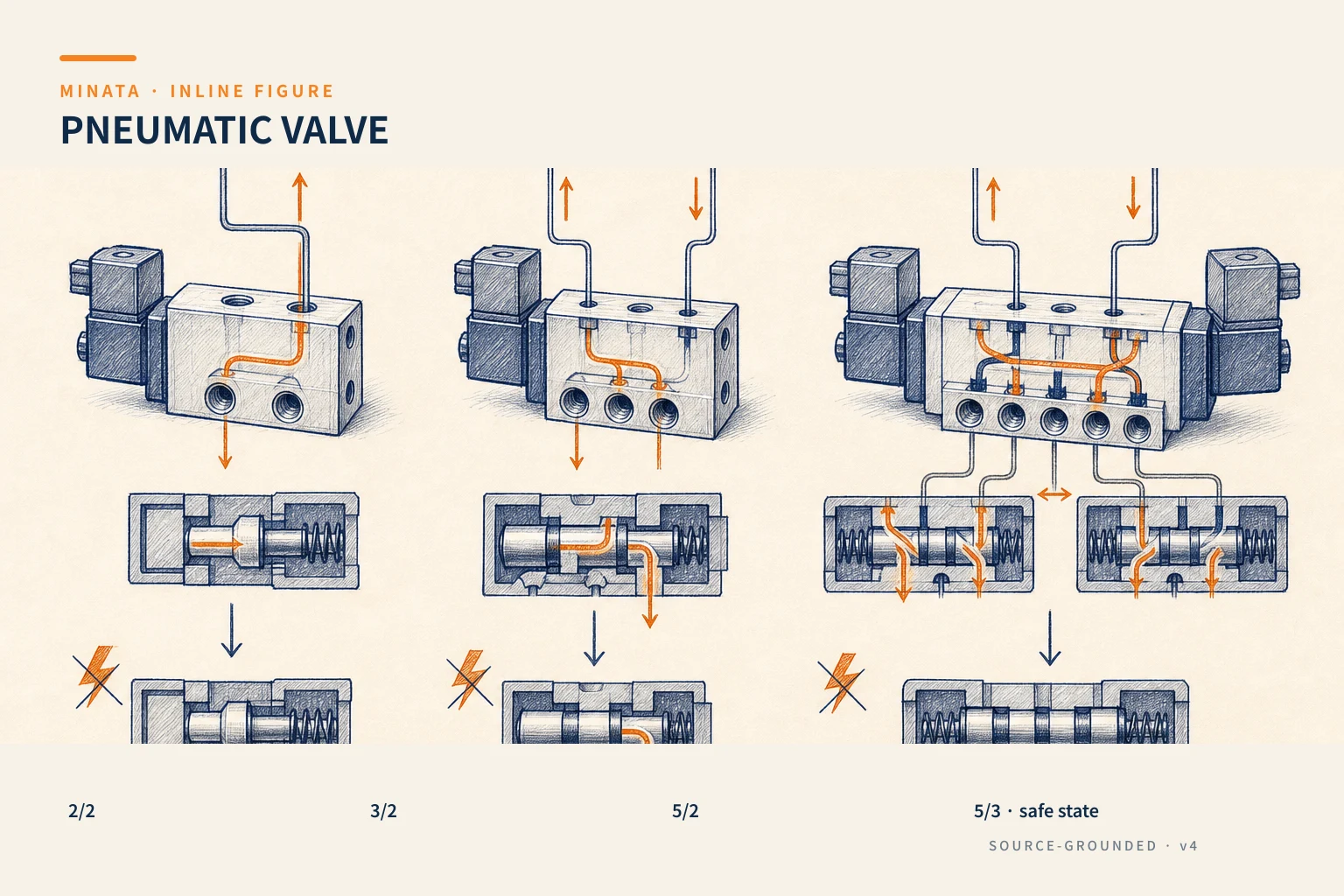
Read the symbol from the mechanism first, not from the valve code
A valve is the element that changes the path of the air. It does not create the motion requirement; the cylinder, clamp mechanism, vacuum cup or pilot is where the requirement originates. Draw the single- or double-acting cylinder, the load direction, the connections and the exhaust line. Then determine, for each valve position, which chamber is supplied and which is exhausted. This approach avoids choosing a 5-port valve for a mechanism that only needs supply–exhaust of one line, or using a 3/2 valve for a double-acting cylinder and then lacking the control line for the other side.
The MISUMI catalog groups 5-port direct-piping, base-piping and 2-port valves in the same pneumatics area. This reminds you that the port count is the first step; the mounting type, manifold, joint, silencer and speed controller are part of the circuit. A valve correct in function but chosen as a stand-alone unit when the machine needs many stations will make the tubing, wiring and maintenance more complex than necessary.
2/2 valve: when you only need to open or block an air line
A 2/2 valve has two ports and two states. It is used for an open/close function: supplying air to a branch, blowing to clean, blocking a line, or supplying a downstream element. The first point is normally closed or normally open. When the coil loses power, is the air line closed or open? The answer must be based on the desired machine behavior, not the type in stock.
A 2/2 valve must also be chosen by flow and pressure, not just thread. A valve with a suitable thread but a small orifice/flow will slow the mechanism, create a pressure drop or make a vacuum generator perform poorly. A long pipe, fittings, filter and silencer all cause loss; read the flow spec of the exact maker and check the pressure condition at the device.
3/2 valve: supply and exhaust of one working line
A 3/2 valve has a supply port, a working port and an exhaust port. It is usually used for a spring-return single-acting cylinder: one state supplies air for the cylinder to run, the other exhausts so the spring/external force returns it. It can also be used for a pilot, blow-off or air signals. Distinguish normally closed from normally open by the symbol: when the coil is not energized, does the working port connect to the source or to the exhaust?
For a clamp mechanism, the power-loss state must be considered together with the load and the risk. An NC valve can exhaust the cylinder chamber on power loss, but that does not by itself prove the clamp is safe or the workpiece will not drop. Some mechanisms must hold the clamp, some must release for safety, some need a mechanical lock. Put this requirement into the risk review, do not infer from the letters NC/NO.
5/2 valve: the common choice for a double-acting cylinder
A 5/2 valve has one supply, two working ports connected to the two cylinder chambers, and two exhausts. When the spool changes position, one chamber is supplied while the other is exhausted, so it suits controlling advance/retract. A single-solenoid valve usually has a spring returning it to the default state when the coil releases; a double-solenoid valve holds/changes position by the energized coil depending on the construction. This is an important difference when the PLC resets, a coil wire breaks or the control power is lost.
For a 5/2 valve, check the mechanism speed by the circuit flow and speed controller, not by choosing a larger coil. Meter-out is often used to regulate the exhaust air and help the motion be more stable in many mechanisms; but the mounting direction and load condition must still be tested. The exhaust needs a suitable silencer/exhaust line, because a dirty or undersized silencer can slow the mechanism and change the cycle.
5/3 valve: choosing the correct center position
A 5/3 valve adds a center position. Three common center configurations create different behaviors: blocking the ports, exhausting the working ports or supplying pressure per a maker-defined symbol. No configuration is "safe by default" for every machine. Center-closed can hold pressure in the chamber but there is still leakage, load, friction and how the cylinder is mounted; center-exhaust can make the mechanism free or lower under load; center-pressure can hold/push per the circuit geometry.
Choose 5/3 when the machine really needs this center state, for example stopping a mechanism in a controlled condition or a circuit design with a special requirement. If the cycle only needs a clear advance/retract, a simpler 5/2 can reduce the number of assumptions in operation. Always read the symbol of the exact model, because the center and pilot symbols can differ between series in the catalog.
Flow, response and mounting type
The valve flow must meet the cylinder volume, cycle speed, supply pressure and tubing. A large-bore or long-stroke cylinder may not reach the cycle time if the valve/tube is too small. Changing to a larger valve while keeping a clogged tube, fitting or filter also does not solve the loss chain. For many valves, a manifold/terminal gathers the supply–exhaust and wiring; in return you must compute the total flow, the station-isolation capability and the maintenance space.
Check the coil voltage, connector type, IP, temperature, duty and manual-override capability. A manual override is useful for commissioning but must be protected so it is not operated by mistake. For a dusty, wet or chemical environment, checking the coil IP alone is not enough: the connector, tube, fitting and exhaust position must also be suitable.
Read the flow as part of the whole air path
The maker's flow spec has defined test conditions. When comparing two models, keep the same representation and read the pressure condition, differential pressure, medium and fitting type too. The valve's nominal flow does not tell the whole real speed if the air still passes through the FRL, small tube, elbows, speed controller and silencer. State clearly on the calculation sheet: the expected lowest source pressure, the regulated pressure at the machine assembly, the inner diameter and length of each branch, the number of mechanisms running at once, and the advance/retract time to reach.
A practical check is to measure the stroke time and the pressure at the valve supply port during an unfavorable cycle, for example when many stations run at once. If the pressure at the valve drops significantly from the source, replacing the valve alone may not solve the cause. That data also helps maintenance distinguish a stuck valve from a dirty filter, a kinked tube, a clogged silencer or a too-closed speed controller. Any change to the tube or fitting should be updated in the air diagram and BOM so the test result stays traceable.
Single solenoid, double solenoid and the control signal
A single-solenoid valve has one coil and a mechanism returning to a defined position when the coil loses power. This is an easy-to-read choice for cycles that only need one clear default state. A double-solenoid valve has two coils to change the spool by two separate commands; the state after losing the command depends on the valve construction, the pilot pressure and the mechanical condition, so the PLC should not assume it returns to the initial position by itself. The valve type must be recorded on the I/O diagram together with the coil logic state, especially when using a transistor output, relay or remote I/O.
Also check the coil's inrush/holding current, rated voltage, polarity if it is a protected DC coil, the connector standard and the wiring direction. A reasonable choice on paper can still cause a commissioning fault if the M8/M12 jack, the wiring or the 24 VDC supply was not sized for the number of coils on at once. For a machine with a diagnostic requirement, determine from the start whether you need to read position feedback, an LED indicator, a pressure switch or an end-of-stroke sensor; a standard valve usually cannot replace a signal confirming the mechanism reached position.
Pilot, low pressure and vacuum applications
Some valves use the internal source pressure to control the pilot. So they have a minimum operating pressure; below this threshold the spool may not change state as expected. SMC distinguishes internal pilot, external pilot and direct operated; an external pilot is used when the main pressure is lower than the minimum or in a vacuum application. This is why you must not infer that every valve marked with the same port count is interchangeable in a vacuum circuit.
When opening/closing a vacuum line, read the correct pressure range, port mapping and pilot condition in the catalog of the chosen series. The exhaust port may need different handling from an ordinary pneumatic circuit. A vacuum system may also need a vacuum-break valve to release the workpiece quickly, a filter to prevent foreign matter entering the ejector/pump, and a sensor to confirm the vacuum pressure. The article choosing a pressure and vacuum sensor explains this confirmation part; here, the valve is just one link in the pick–hold–release sequence.
Placing the manifold for convenient operation and replacement
A manifold is worth considering when a station has many valves of the same type: the number of supply/exhaust points, the wiring and the mounting space are reduced, and the station numbering is clearer. Before locking the approach, record the valve position on the layout, the connector direction, the valve-removal clearance, the tube-insertion position and the exhaust line. A manifold placed against the frame wall but with no way to remove a station while the tubes are still in place turns a few-minute replacement into dismantling the whole assembly.
Points to lock with the supplier include: the number of stations used now and in reserve, the base/blanking-plate type, common supply/exhaust or how to separate zones, the electrical connection, fieldbus or multi-pin, and spare coils/valve cartridges. If the cylinders have different pressure requirements, do not assume that a common manifold supply is reasonable; consider the regulator zone, the simultaneously running branches and the lockout procedure during maintenance. The circuit drawing should show station labels matching the labels on the machine and the I/O list.
Separating cycle control from the safety function
A directional valve serves the process control, but it does not by itself make a system a safety function. When a person enters the danger zone, the solution may need to lock/cut the air supply, exhaust the pressure in a controlled way, monitor pressure, use a mechanical load-holding mechanism, or a safety architecture assessed per the applicable standard. How to implement it depends on the machine risk assessment and the project requirement.
In the review, describe the consequence of each fault: loss of 24 VDC, loss of air pressure, a broken coil, insufficient pilot pressure, a tube popping off, an E-stop, and startup after an E-stop. Then determine whether the mechanism is allowed to move or must stand still, who confirms the area is safe, and which state may be reset. Writing these conditions before locking the 5/3 center state is far clearer than trying to assign a safety meaning to a valve symbol.
The data sample to have before requesting a quotation
A useful valve requirement should state: the air diagram marking the de-energized state, the mechanism type and bore/stroke if it is a cylinder, the medium, the source pressure range, the flow/cycle-time requirement, the number of valves operating at once, the mounting type, the connection ports, the coil voltage, the environment, the protection rating, the wiring/fieldbus requirement, and the replacement requirement. Including a layout photo or a mounting-space drawing helps avoid choosing a connector that hits the frame or an exhaust pointing into a dirty zone.
After receiving the model, cross-check the catalog symbol against the intended diagram rather than just comparing the part number. Run a single-operation test, a continuous cycle and a low-pressure situation before acceptance. Save photos of the tube state, the PLC timer values and the measured pressure in the machine file; the next upgrade will know why the current valve was chosen.
The selection sequence by the circuit
- Determine the mechanism: open/close an air line, single- or double-acting cylinder, vacuum or pilot.
- Draw the running, normal-stop, power-loss, E-stop and maintenance states at the mechanism.
- Choose 2/2, 3/2, 5/2 or 5/3 by the air lines needing supply/exhaust and the center state.
- Choose single/double solenoid, voltage, wiring, manual override and feedback when needed.
- Check the valve flow together with the tube, fitting, filter, silencer, speed controller and cycle time.
- Test both at the lowest pressure and when many mechanisms run at once.
Common selection mistakes
- Choosing the port count by habit without drawing the cylinder states.
- Calling an NC valve fail-safe without checking the load/mechanism when the chamber exhausts.
- Choosing the correct thread but not checking the tube–fitting–silencer chain flow.
- Using a 5/3 center-closed to "hold" a load then ignoring leakage, load and the safety review.
- Leaving the manual override, connector, IP and valve-replacement method out of the maintenance design.
Quick selection checklist
- [ ] Have you drawn the supply, working and exhaust lines for each mechanism state?
- [ ] Only open/close one line? Yes → consider a 2/2 valve.
- [ ] A single-acting cylinder/pilot needing supply–exhaust of one working port? Yes → consider a 3/2 valve and NC/NO.
- [ ] A double-acting cylinder advance/retract? Yes → consider a 5/2 valve by single/double solenoid.
- [ ] Do you need a defined behavior at the center position? Yes → read the correct center state of the 5/3 valve.
- [ ] Have you checked the whole-circuit flow and the power-loss/E-stop state?
MINATA can work with the machine team to review the air diagram, flow, valve manifold and mechanism state before locking the BOM. Talk to the Engineering & Manufacturing team.
References
View all MINATA technical articles