Device Selection #07: Pressure/Vacuum Sensors — Choosing by Range and Output Type
Choose a digital pressure switch when the machine only needs to decide whether a pressure or vacuum threshold is reached or not; choose a sensor with analog output when the PLC/HMI needs to see a continuous value for diagnostics, data logging or control; choose the correct vacuum, compound, low-pressure, positive-pressure or differential-pressure range by the real value the sensor port will see. Do not choose by the unit shown on the HMI or by the nominal pressure of the air source: the range, the reference pressure type, the medium and the output must match the mounting position.
In a pneumatic system, the two most time-consuming mistakes are usually setting the sensor to the wrong range and using an on/off signal to answer a question that actually needs a continuous trend. A vacuum cup may signal "vacuum reached" yet still leak periodically; an air line may still hold pressure but sag when several valves open at once. This article helps separate the monitoring, control and diagnostic functions clearly before locking a model.
Quick comparison
| Criterion | Digital pressure/vacuum switch | Analog pressure sensor | Differential-pressure sensor |
|---|
| Data returned | One or more threshold states | A continuous value over the scaled range | The pressure difference between two ports/points |
| Suits | Interlock, vacuum-reached signal, level alarm | Trend, recipe, leak assessment, control/monitoring | Filter clogging, pressure drop across an element, indirect level/flow by design |
| Common output type | NPN/PNP open collector; relay depending on model | Voltage or current, per the datasheet | Analog or switch depending on model |
| What to choose | Range, setpoint, hysteresis, NO/NC logic | Range, unit/scale, 0–10 V/1–5 V/4–20 mA signal depending on model | The two pressure-tap points, positive/negative side, per-port pressure limit |
| Advantage | Compact logic, simple digital I/O wiring | Data to see the degradation level and adjust thresholds | Measures the true difference quantity when the application needs it |
| Risk if misused | Cannot see the leak/pressure-sag trend | Wrong scale or signal noise gives false data | Miswiring the ports or wrong pressure limit damages/misreads |
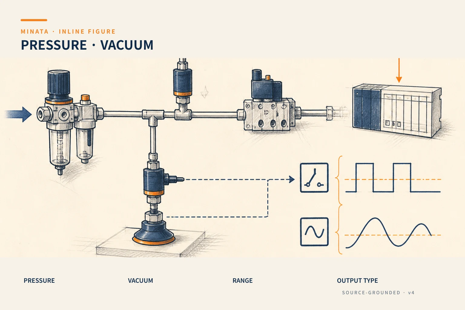
First step: name the pressure type correctly
The word "pressure" used on the shop floor can mean several different quantities. On the specification and the P&ID/I/O diagram, state clearly which type the sensor measures.
- Gauge pressure: pressure relative to atmosphere. This is the familiar representation for supplied compressed air and many pressure switches.
- Vacuum: pressure below atmosphere. A vacuum-switch catalog may list a range from 0 to a negative value in the gauge reference; do not flip the sign or mix units when scaling the PLC.
- Compound pressure: a range that crosses the atmospheric point, useful when a port can be both vacuum and positive pressure within a cycle.
- Absolute pressure: referenced to a perfect vacuum; must be distinguished from gauge when the process, external data or spec states absolute.
- Differential pressure: the difference between two ports. It is not a single-port pressure sensor renamed; the pressure-tap method and the limit at each port must both be designed.
The SMC documentation for pressure/vacuum sensors lists vacuum, compound, low-pressure, positive-pressure and low-differential-pressure ranges separately, and also offers NPN/PNP and analog output options. This is a useful hint for writing the requirement: first choose the range type, then choose the resolution, connector and output.
Choosing the range: the working zone matters more than the maximum number
Write down the lowest and highest pressure and the setpoint at the sensor port under real operating conditions. That value must include startup, exhaust, valve switching, several mechanisms running at once, and air-source deviation. The catalog range must cover these states within the manufacturer's stated limits; do not use proof pressure or burst pressure as the working zone.
Practical selection rules:
- Measuring a vacuum cup's vacuum: choose a vacuum range whose real working zone sits within the rated range. If a suction cup only needs to confirm it holds the workpiece, the setpoint must be tested with the actual material/workpiece and motion cycle, not copied from another machine.
- Monitoring compressed-air pressure: choose a positive-pressure range suited to the line to be monitored. Place the sensor after the regulator if the goal is to know the pressure at the machine assembly; placing it at the source only tells you the common supply, not the loss to the mechanism.
- A line switching between suction and blow: consider a compound range instead of forcing a vacuum/positive-only sensor to work at the edge of, or beyond, its range.
- Monitoring a clogged filter or loss across an element: consider differential pressure and the two-side pressure-tap positions. Two single-port sensors subtracted in the PLC can work, but you must evaluate the total error, sampling and the case of losing one sensor.
There is no "wider range is always safer" for every goal. Too wide a range can make the change you care about occupy only a small part of the signal. Too narrow a range risks over-pressure when the machine faults. This balance must be based on the range/accuracy of the exact model, not inferred from another series.
When a digital pressure switch is enough
A digital pressure switch changes state when the measured value crosses above or below the setpoint, usually allowing a hysteresis setting and possibly one or two outputs. It suits when the operating decision only needs a discrete signal.
Examples:
- Allow the robot to lift the workpiece only when vacuum has exceeded the tested acceptable level.
- Alarm when the pressure supplied to a clamp fixture drops below the operating threshold.
- Confirm the regulator or air supply has recovered before resetting the cycle.
- Reroute or stop the station when pressure is too high/low per the requirement.
When choosing a digital switch, do not just choose the setpoint. You must check:
Hysteresis and signal chatter
If the pressure fluctuates around a threshold, the output can toggle continuously when the hysteresis/setpoint is unsuitable. Hysteresis is the gap between the switch-on and switch-off points; the value must be enough to avoid chattering but not so large that the logic no longer reflects the process requirement. Some models allow a time delay or a digital filter; use these functions after understanding the real fluctuation, rather than to mask a leaking pipe or an unstable regulator.
PNP, NPN, NO/NC and output load
The SMC datasheet shows pressure sensors with an NPN or PNP open-collector output and analog options. The PLC/remote I/O decides the wiring type; a transistor output is not a dry contact. Check the supply voltage, the input common, the load current, the NO/NC logic type and the pinout before replacing a sensor. When the logic involves machine stop/alarm, define clearly how the PLC handles the wire-break or power-loss state.
The display function does not replace I/O verification
The display on a pressure switch may show the unit, setpoint and alarm, but the output to the PLC still needs testing with a gauge/trend or the actual displayed value. During FAT/SAT, cross the pressure through the threshold, confirm the I/O bit, the machine sequence, the hysteresis and the recovery after an alarm. Save the setpoint/parameter backup with the machine file.
When you need an analog output
An analog output brings a continuous value from the sensor to the analog input of a PLC, remote I/O, controller or recorder. It is needed when the question is no longer "reached yet?" but "how much is it now, how is it changing, and how is it decreasing?". SMC has series that state voltage/current output depending on the model; 1–5 V, 0–10 V or 4–20 mA cannot be treated as the same signal just because they are all called analog.
Choose analog when you need to:
- Plot the vacuum trend per cycle to detect leaks, a dirty filter, changing workpiece surfaces or an ageing cup.
- Monitor the pressure after the regulator to detect a pressure sag when several actuators operate.
- Log quality data or run a recipe with several threshold levels.
- Feed the value to a control/monitoring algorithm with a clear requirement.
Choose voltage or current by the system, not by habit
An input module only supports certain signal types. A 1–5 V sensor needs a voltage input and its own scaling; a 4–20 mA sensor needs loop wiring, a supply, a current input and a check of the loop limits per the datasheet. For long cables or noisy environments, the current standard is often considered because its transmission differs from voltage, but that does not allow ignoring the cable routing, shield, grounding and common per the manufacturer's guidance. Read the wiring diagram of both the sensor and the I/O module.
The scale must be saved and verified
The PLC/HMI needs to know which raw value corresponds to the low/high end of the sensor range. Do not hard-code a formula from a feeling based on the pressure number printed on the screen. Take the range and output signal from the datasheet of the exact part, configure the unit, then verify with a suitable reference pressure/vacuum source or calibration device. When switching to a different range, update the tag description, scale, alarm and screen at the same time.
Analog does not solve noise or wrong sampling by itself
The signal can fluctuate due to real pressure, valve switching, sensor placement, sample rate or wiring. Setting a filter/time average must consider the application's dynamics; over-filtering makes the alarm arrive late, under-filtering fills the HMI with noise. State clearly the response time needed for an interlock, and use a separate digital switch if a filtered analog signal cannot respond in time to the requirement.
Vacuum sensors for suction cups: where to place the sensor?
The mounting position decides the meaning of the reading. A sensor near the ejector/generator tells the vacuum-source state there; a sensor near the suction cup better reflects the loss along the tube and at the suction assembly. There is no universally correct position for every machine. Consider the tube length/diameter, vacuum valves, multiple branches, volume, workpiece surface and the sampling moment in the cycle.
A test procedure can include:
- Mount the suction cup with the worst-case workpiece for roughness, curvature or edge leak within the expected range.
- Record the pressure/vacuum at suction start, at hold confirmation and while the robot/gripper accelerates.
- Test a missing, tilted or holed workpiece to see whether the threshold can distinguish the case that must be rejected.
- Lock the setpoint/hysteresis/delay from the test data, recording the cup model and the workpiece material.
- Re-check when changing the cup, ejector, tubing or recipe, because the old setpoint may lose its meaning.
A switch confirming vacuum can be part of an operating interlock, but does not by itself make the lifting assembly a safety system for people. If a dropped workpiece risks harm, you need a risk analysis and a holding/guarding/monitoring measure per the machine's safety design.
Compressed-air pressure: measure the source or at the mechanism?
The pressure at the compressor, FRL, manifold and cylinder port is not necessarily the same when the machine runs. Small piping, a dirty filter, a distant regulator, valve switching and simultaneous flow demand all create a pressure drop. So the requirement must name the exact point: "source pressure after the FRL," "supply pressure into the clamp circuit," or "pilot pressure at the valve."
If the goal is only to signal a general loss of air, placing the sensor at the source may be reasonable. If the goal is to detect insufficient clamping force or an actuator running slow due to a pressure sag, the sensor must be near that assembly and the logic must consider the moment in the cycle. Avoid using a pressure value as a direct formula for clamping force without accounting for the cylinder bore, friction, force-transmission mechanism and losses; the pressure value is only one input to the mechanical problem.
Port, thread, medium and mounting conditions
An electronic sensor is also a pressure-bearing element. Choose the port/thread, the wetted material, the seal, the mounting orientation, the cable/connector and the protection rating by the medium and position. Do not tighten by the plastic body/display if the datasheet requires a hex/other tightening point. Do not use an adapter of unclear thread standard between BSPP, NPT, Rc or other standards; a geometrically matching thread can still leak or crack if the sealing principle is wrong.
For water, oil or gas with contaminants, check media compatibility and the risk of the pressure-tap port clogging. In a vibrating environment, use a bracket/support tube so the sensor and fitting do not take load from the piping. When using vacuum, check for leaks at the fitting with a suitable test before blaming the sensor.
Three quick selection situations
A station picking bottles with vacuum cups
If the robot only needs a "bottle picked" interlock and the cycle is stable, a digital vacuum switch with a range and setpoint tested on real bottles is the starting point. If a leak fault appears gradually over days or you need to log a trace, add or switch to an analog trend to see the vacuum amplitude. Place the sensor at the position that reflects what needs protecting: near the cup, or at the generator with a clear technical reason.
A pneumatic clamp fixture that must signal low pressure
A digital pressure switch placed after the regulator/clamp circuit can warn of adequate pressure before the cycle. The setpoint must be related to the clamping-force test of the real mechanism, not the compressor source pressure taken as the standard. If a pressure sag occurs when several stations run, an analog trend at the manifold/clamp assembly helps find the cause and assess capacity.
Monitoring an air filter/process line
If the requirement is to know the pressure drop across a filter, you must measure the difference across the two sides. A differential-pressure sensor is the direct choice when the pressure condition at each port is suitable. If using two gauge sensors to compute in the PLC, verify the simultaneous calibration, sampling lag and per-sensor error handling before using the result for a maintenance alarm.
Common mistakes
- Choosing a vacuum sensor then using it on a line that can go positive. Determine compound/positive/vacuum by the real state of the port.
- Taking too narrow a range based on nominal pressure. Account for startup, transient and fault situations within the model's limits.
- Using analog but configuring the wrong range or 1–5 V/4–20 mA type. Scale per the datasheet of the exact part and verify with a reference device.
- Using a digital switch to analyze a slow leak. It only tells you the threshold was crossed; use analog/trend when you need the trend.
- Placing the sensor at the source then concluding the pressure at the cup/cylinder. Measure at the point meaningful to the requirement.
- Replacing a fitting/thread of the wrong standard and blaming the sensor for the leak. Check the thread, seal, torque and medium.
Quick selection checklist
- [ ] Does the sensor port measure gauge, vacuum, compound, absolute or differential pressure?
- [ ] Are the low/high value and transient at the exact mounting point recorded?
- [ ] Does the model's rated range cover the working zone, and is proof/burst not used as the range?
- [ ] Do you need a threshold interlock or continuous data to trend/diagnose?
- [ ] Do the NPN/PNP, NO/NC or analog type match the I/O module and the wiring diagram?
- [ ] If analog, are the range/signal/unit and scaling formula taken from the datasheet of the exact model?
- [ ] Are the port, thread, seal, medium, vibration and protection rating suited to the mounting position?
- [ ] Have the setpoint/hysteresis/delay been tested with the real workpiece, tubing and cycle?
If you are choosing a pressure/vacuum sensor for a picking assembly, a clamp fixture or a process air line, MINATA can review the real range, mounting point, I/O and alarm logic with you before locking the BOM. See MINATA's Engineering & Manufacturing service.
References
- SMC Sensors leaflet — an example of vacuum/compound/positive/differential pressure ranges and NPN/PNP/analog output options by model.
- SMC PSE-C Pressure Sensor Controller catalog — an example of vacuum, compound, low-pressure, positive-pressure ranges and voltage/current output; reconfirm against the current part number.
- SMC XSE4X Installation & Maintenance Manual — an example of NPN/PNP/analog wiring and operating conditions that must follow the specific model manual.
- MISUMI, FA Factory Automation 2018 — Sensors/Switches — reference for the sensor/switch selection structure; catalog scans are not used in the public article.
More in the Device Selection series
View all MINATA technical articles