Device Selection #20: Vacuum Cups — Pads by Workpiece Surface and Weight
Choose vacuum cups by starting from the real workpiece: is the surface airtight, what is the weight and where is the center of gravity, how much lateral force/moment does the motion create, and how long does the machine have to reach the vacuum threshold. Only then choose the pad shape, material, diameter, number of pads, buffer, vacuum source and confirmation sensor. The theoretical lifting force is a reference calculation step; the final decision must be tested on the workpiece, in the cycle and under the real surface conditions.
Quick comparison
| Pad type/solution | When suitable | To check carefully | Limit to remember |
|---|
| Flat pad | Flat, hard, airtight surface | Sealing, diameter, lateral force | Hard to compensate height difference or warp |
| Ribbed/grooved pad | Textured surface, needs more contact stability | Marking, friction, orientation | Does not replace the force/moment check |
| Bellows pad | Changing height, slightly curved surface, needs stroke compensation | Bellows stroke, stability under acceleration | Can be softer against lateral force/moment |
| Oval/long pad | Rectangular, narrow or long workpiece | Center-of-gravity position, orientation | Must avoid creating a large moment at the workpiece edge |
| Sponge/foam or special pad | Rough, carton, uneven surface, easily marked object | Air leak, dust, durability, real test | Higher demand flow, life varies with the environment |
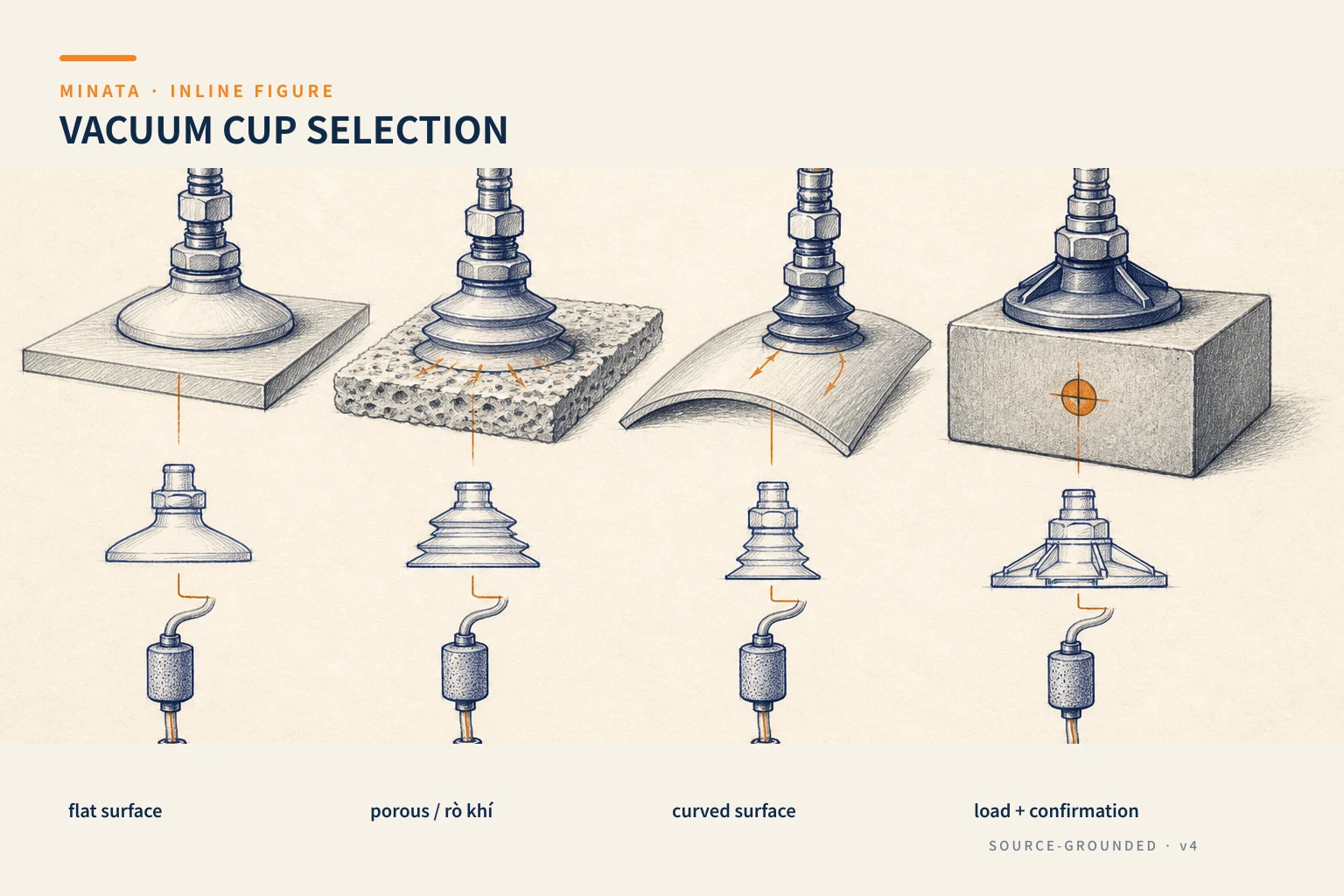
Start from the workpiece, not from the cup diameter
A vacuum cup only creates good force when the pad lip seals against the surface. So the first specification is the workpiece data: material, size, minimum/maximum weight, flatness, curvature, holes, ribs, oil, dust, porosity, temperature, finish and the marks allowed to be left. If the workpiece changes between lots or suppliers, take a representative sample in the worst-case condition, do not use one clean, flat sample to lock the configuration.
Determine the picking direction and the acceleration direction. Lifting from a horizontal surface mainly uses the lifting force perpendicular to the surface. Pulling a workpiece on a vertical face or in horizontal motion needs the friction force between the pad and the workpiece considered; this is a situation far more prone to slipping. SMC emphasizes that a pad is sensitive to shear force parallel to the surface and to moment, and recommends reducing the moment by considering the center of gravity, reducing the acceleration, and avoiding lifting from a vertical face where possible. These notes must be in the end-effector layout, not just in the calculation notes.
Draw the picking position, the workpiece's center of gravity, the pads, the robot/gantry acceleration direction and the obstacles. With multiple pads, the load distribution changes with the height error, frame stiffness, buffer stroke and workpiece surface; do not assume each pad takes an equal share. If one pad is open, do the remaining pads hold the workpiece enough? This question guides the choice of an independent vacuum circuit, a vacuum-saving valve or a per-zone sensor.
Use the theoretical lifting force to screen, not to skip testing
The theoretical lifting force originates from the pressure difference between atmosphere and the vacuum level, times the pad's effective area. A round pad's area increases with the square of the diameter, so a small change in diameter can have a large effect on the computed force. But the effective area and the real pressure difference are usually lower than assumed if the pad does not seal, the workpiece is curved, there is oil/dust, the tube leaks, the filter is dirty or the ejector does not reach the supply condition. So do not treat one computed force number as a commitment for every surface.
Build a calculation sheet with the workpiece weight, lifting direction, number of pads, the measured/guaranteed vacuum level, a safety factor for the motion condition, the lateral force, the moment and the load-distribution assumption. SMC describes the selection process: determine the position, number and diameter of pads by workpiece balance; find the theoretical force from the area and vacuum pressure; use a safety factor by the lifting method and transfer condition; then confirm with a suction test. This is a better sequence than choosing a pad by shape and hoping the force is enough.
If an internal formula uses units or a conversion factor, record the unit and the source of the factor clearly. A more reliable way is to use the exact maker's curve/table for the exact pad, material and condition, then run a test on the workpiece. For a high-risk application, an expensive workpiece or motion through an area with people, assess an anti-drop measure separately; vacuum holding should not be the only measure if the consequence is severe.
Choose the pad shape by how the surface makes contact
A flat pad usually suits a hard, airtight flat surface. A ribbed/grooved pad can help grip some surfaces and support contact stability, but the choice must be based on the workpiece/test sample, not just the pad-type name. A bellows is useful when you need to compensate a height difference, approach a curved workpiece or reduce the effect of a mounting misalignment. In return, the softness and compensating stroke can make the end-effector react differently under acceleration, so check the lateral force/moment and the workpiece-contact sequence.
An oval pad suits a narrow, long or rectangular workpiece when you need a contact area along one direction. The oval orientation must be parallel to the workpiece geometry and the intended force path. A deep/bowl pad can handle special shapes; a foam/sponge pad suits an uneven surface in some applications but you must account for leakage, dust and the flow demand. SMC's pad-shape list includes flat, bellows, oval, heavy-duty, mark-free, sponge and many variants; this is why you must look at the geometry and surface before comparing part numbers.
When the workpiece surface easily marks, choose a special pad/material and test the marking under the real contact-time condition. SMC has a mark-free line for cases where no suction mark may be left on the workpiece, but this does not fully eliminate testing on the real finish. The effect can change with heat, the initial contact force, surface oil, hold time and the pad's age. Save photos of the acceptance criterion together with the workpiece sample in the quality file.
Pad material: choose by compatibility, not by perceived softness
The elastomer material affects the sealing ability, friction, abrasion resistance, heat, marking, electrical resistance and oil/chemical compatibility. There is no "best rubber" for every workpiece. A soft material can seal well on an uneven surface but wears/marks differently from a hard material; an oil- or heat-resistant material must be confirmed by the manufacturer's compatibility table. If food, pharma or a material with a special requirement is involved, request the documentation and usage limit of the exact product part number, do not infer from the material name.
A pad is a wear item. SMC notes that rubber degradation depends on the environment and operating condition, so the life cannot be estimated in advance from the catalog alone. Determine a checkable replacement criterion: cracking, deformation, a sticky surface, a longer time to reach vacuum, workpiece slipping, the number of cycles or a periodic-test result. Record the model, batch if traceability is needed, and the mounting method so the replacement pad is not twisted or deformed.
Number of pads, position and center of gravity
The number of pads is not just to add lifting force. The pads must be arranged to support the workpiece in balance and limit the moment about the frame. Placing two pads too close to the center while the workpiece is long can create sag/moment at the edge; placing them too far apart can hit a hole, rib or weak area. For a workpiece with an off-center gravity, adjust the position or number of pads by the load model and confirm with a test in the unfavorable orientation.
Multiple pads must cope with the workpiece-face error. A buffer or ball joint can compensate part of the height/angle, but also changes the dynamic load. The end-effector mechanism must be stiff enough for the pads to contact in a controlled sequence, not concentrating force on the first cup. If one position sometimes has no workpiece, determine whether the circuit blocks the open path; an open path can pull down the vacuum of the whole zone and lengthen the suction time.
For picking from a vertical face, the holding force depends heavily on friction, so just increasing the diameter may still not be enough if the surface is slippery or the acceleration is large. Optimizing the picking direction, adding a mechanical support, reducing the acceleration or changing the picking principle may be more reliable. SMC advises a sufficient safety factor when forced to lift from a vertical face; that emphasizes this is a case to test specially, not to apply a vertical lifting-force table mechanically.
Air leak, tube, filter and vacuum source
The vacuum source can be a pneumatic ejector or a pump, but the common point is that it must reach the vacuum level and flow needed for the system's volume/leakage. An ejector needs the correct supply pressure per the catalog condition; so its supply circuit must be checked together with the FRL, valve and tube. A pump needs consideration of the piping, filter, ability to serve multiple zones, heat and maintenance. Do not choose the source by the maximum vacuum figure alone; the response time and the leakage-compensation ability decide the real cycle.
A porous workpiece such as carton, paper, a rough surface or a holed workpiece creates leakage. SMC notes that you must confirm the air permeability when choosing a pad for carton. For this workpiece type, testing measures the real leakage flow rather than assuming from the material. A long tube or an unsuitable diameter increases the volume to be evacuated and delays reaching the threshold; a filter protects the source from dust/debris but must also be sized and maintained so it does not choke the circuit.
Split the vacuum into zones when many pads or many workpieces have different conditions. A vacuum-saving valve, check valve or a per-branch isolation solution can be useful depending on the diagram, but you must read the vacuum/flow range and logic of the exact model. Test the situation of losing one pad, an off-position workpiece, a slightly dirty filter, low supply pressure or a start-of-shift startup. If you only test "one pad, one workpiece, once," the system rarely reveals its weak points.
Response time and the pick–release sequence
The time from the valve command to reaching the vacuum setpoint includes the valve time, tube, volume, leak, ejector/pump and the pad contacting the workpiece surface. When the cycle time is tight, do not ignore this time and then speed up the robot. Use a vacuum sensor to confirm suction before lifting; set a timeout logic and fail-to-pick handling so the machine does not move without the workpiece. The article choosing a pressure and vacuum sensor explains how to choose the sensor by range and signal.
Releasing the workpiece must also be designed. Some cases need a blow-off or vacuum-break valve to release quickly, but the air amount and timing must be tuned so it does not blow the workpiece off-position, dirty the process area or create a risk for people. If the workpiece must be placed accurately, check the final motion, the pad sinking, the guide/locator position and the release time. A vacuum cup is only part of the end-effector; the placement accuracy usually comes from the locator or a guiding mechanism.
Fail-safe and protecting people, workpiece, machine
Loss of the air source, power loss, a valve fault, a broken tube or loss of vacuum can all drop the workpiece. A vacuum switch helps detect the state, but does not hold the workpiece by itself. Determine the consequence of a dropped workpiece: product damage, fixture damage, machine obstruction or danger to people. High-consequence cases need suitable added measures such as a mechanical support, an exclusion zone, controlled speed/motion direction, early detection or an assessed safety architecture.
Do not treat the pad as a long-term holding mechanism unless the manufacturer and the system design allow it in a defined condition. SMC clearly writes that a vacuum pad is not designed to hold vacuum and requires a suction test on the real equipment to determine usability. In the design, define the maximum hold time, the behavior on alarm, the pressure-exhaust/lockout method for maintenance and the recovery approach when a pick fails. These must be reflected in the PLC sequence, HMI alarm and operating instructions.
A handover-ready selection process
- Collect the worst-case workpiece sample: weight, finish, flatness, porosity, oil/dust, heat and the no-mark requirement.
- Draw the picking direction, center of gravity, pad points, lateral force/moment and the acceleration profile.
- Preliminarily choose the pad shape/material/diameter/number; compute the reference force with the real vacuum and a safety factor with recorded assumptions.
- Choose the frame, buffer/ball joint, pad position and check for collision/space over the whole travel.
- Size the ejector/pump, valve, tube, filter and zone by the leak and the required suction time.
- Choose the vacuum sensor, pick-confirmation logic, timeout, release/blow-off and the fault scenario.
- Test with the real workpiece under dirty, orientation and unfavorable-cycle conditions; save the result before locking the BOM.
Mistakes to avoid
- Choosing the cup by weight alone without considering the center of gravity, acceleration and lateral force.
- Taking the theoretical force at the ideal vacuum level as the committed operating force.
- Assuming multiple pads always share the load equally when the workpiece is curved or the frame is soft.
- Using one vacuum zone for pads that can be open without checking the leak and response time.
- Dropping the filter and letting dust/debris enter the ejector or pump.
- Believing the vacuum switch or a pressure-holding valve will by itself prevent a workpiece drop when the source is lost.
Checklist before locking the BOM
- [ ] Have you tested the pad on a workpiece sample representing the worst-case condition?
- [ ] Are the weight, center of gravity, motion direction, lateral force and moment in the calculation sheet?
- [ ] Do the shape, material, diameter, number of pads and buffer match the surface and the marking requirement?
- [ ] Does the computed force use the real vacuum level, a safety factor and a recorded load-distribution assumption?
- [ ] Do the ejector/pump, valve, tube, filter and zone reach the leak and real response time?
- [ ] Have the suction-confirmation sensor, timeout logic, release and pick-fail handling been tested?
- [ ] Have the loss-of-vacuum/source measure and the workpiece-drop risk been assessed?
MINATA can work with the machine team to test the end-effector on the real workpiece, review the vacuum source, the suction-confirmation logic and the handover file before locking the BOM. Talk to the Engineering & Manufacturing team.
References
- MISUMI, Factory Automation Catalog 2018, Vacuum equipment chapter; cross-checked against MINATA's internal catalog on 2026-08-23.
- SMC, Vacuum Pad Selection Procedures, used to cross-check the selection sequence, theoretical force, lateral force/moment and the suction-test requirement.
- SMC, Vacuum Pads — Select from the Shape, referencing the pad-shape groups.
- SMC, Vacuum Equipment Model Selection, referencing the leak, response time, sensor and filter content in a vacuum system.
View all MINATA technical articles