Device Selection #12: Brakes and Clutches — Choosing by Load Holding and Power-Loss Safety
Short answer: choose a spring-applied, electrically-released holding brake when a shaft must stand still safely in the power-loss state; choose a dynamic stopping brake by the braking torque, inertia and thermal energy of each stop; choose a clutch when you need to engage/disengage the torque path on command without necessarily stopping the motor. The three devices are often lumped together as "brake motor," but their task, fail-safe state and thermal limit differ greatly. For a hanging load, a guard, a lift table or a shaft with people nearby, defining the load-holding mechanism must not be left to the end of the drawing.
Quick comparison
| Device | Main task | Common state on power loss | What to choose | Typical application |
|---|
| Spring-applied holding brake | Hold a shaft still | Spring clamps the brake, the shaft is held | Holding torque, air gap, release time, cycle | Z axis, doors, lift table, servo motor with brake |
| Dynamic stopping brake | Absorb energy to decelerate/stop | Depends on the control architecture | Braking torque, inertia, thermal energy, number of stops | Winding drum, rotary axis, machine with emergency stop |
| Electromagnetic/mechanical clutch | Connect or separate torque transmission | Depends on the normally engaged/disengaged type | Transmitted torque, engagement speed, slip heat, cycle | Selecting a mechanism, engaging a drive, packaging machine |
| Mechanical brake outside the motor | Hold/stop at the load | Depends on the fail-safe design | Torque at the load, mechanism, person protection | Heavy load, lifting mechanism, device with its own safety requirement |
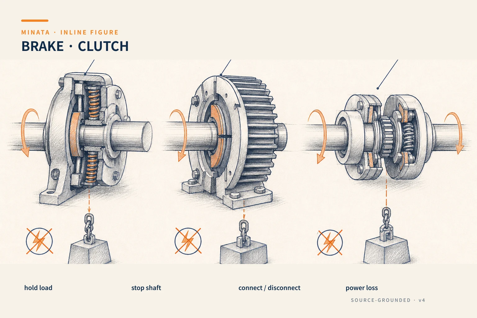
Name the task correctly before choosing a model
A brake can be described by torque, voltage and size, but those three data do not say what job it is doing. A holding brake holds a shaft after it has stopped. A stopping brake decelerates a moving inertia, turning energy into heat. A clutch connects or separates torque transmission between the drive source and the load. The same motor assembly may need both a holding brake and a way to brake dynamically through the driver/inverter; an element that does one job well may not withstand the other.
Start with a state diagram: when the machine runs, stops normally, emergency-stops, loses power, loses air, has a safety-circuit fault and is under maintenance — what is the shaft/load allowed to do? Then ask the question by the load, not just at the motor shaft: at what height is the load, is there a reduction mechanism, can it drift under gravity or spring force, are there people in the danger zone? This diagram decides whether you need a fail-safe brake, a mechanical lock, a load-holding valve or another independent solution.
Spring-applied brake: closed when de-energized
A spring-applied brake is usually mounted near the motor. A spring creates the clamping force on the friction surface to hold; an electric coil is energized to release the brake when the shaft needs to run. The "closed on power loss" architecture is useful for a fail-safe task: if the control power is lost, the brake returns to the holding state instead of releasing the load. KEB describes this brake type as closed when currentless and usable as a holding brake to ensure a safe stop in the de-energized state.
That does not mean every motor-mounted brake is a complete safety mechanism. A holding brake is usually designed mainly to hold after the shaft has stopped. If used to brake a high-speed or high-inertia shaft in every cycle, the friction surface can overheat and wear quickly. The manufacturer's catalog separates limits such as static torque, dynamic braking work, number of stops, switching time, air gap and lifetime. Reading the correct data set by the task is mandatory.
For a vertical axis, convert the required holding torque to the brake position. The load, drum/pulley radius or screw lead, reduction ratio, mechanism efficiency and auxiliary forces affect the result. The safety factor must be based on the maximum load, friction change, mounting error and the approved safety approach. Do not infer the brake torque from the motor power alone: the motor may be small, but a hanging load after reduction still creates significant holding torque at the load.
The brake release and engage time also affects the control sequence. For a servo, you need logic for the driver to create torque before releasing, and controlled deceleration/holding before the brake engages. If you release the brake before the motor creates torque on a Z axis, the load can drop a bit. If you cut the torque before the brake is fully engaged, the shaft can also drift. The brake sequence and feedback signal must be confirmed through the maker's documentation and tested under real load conditions.
Stopping brake: heat is a design parameter
Braking a rotating inertia must absorb energy. This energy turns into heat on the friction surface, a braking resistor or a regeneration path depending on the architecture. One stop may not heat the brake much, but many stops close together accumulate heat. So braking torque is only part of the sizing; the number of stops, the initial speed, the reflected inertia, the rest time and the ambient temperature are all in the decision.
In a servo system, the driver can decelerate by regenerating energy into the DC bus. If the energy exceeds the bus's absorption capacity, the system may require a braking resistor or a regeneration module per the driver's guidance. In an inverter–induction system, similar logic exists at the inverter level. A mechanical brake can be used for an emergency stop or holding, but distinguish it from a frequently repeated deceleration approach. Choosing "a bigger brake" without checking the braking work per cycle can still fail due to overheating.
A large-inertia load such as a rotary table, winding drum, fan, large pulley or a mechanism with a gearbox must be reflected to the braked shaft. Rotating and translating loads can both create significant energy at stop. Setting the stopping speed too abruptly also creates a large mechanical force on the coupling, gearbox, belt and fixture. Read #11 on couplings to see why the peak torque and shock load must be carried into the coupling-selection step.
Clutch: choose to connect/disconnect the drive on purpose
A clutch performs the opposite task to a brake in the basic sense: it connects a rotating source to a load. An electromagnetic clutch can engage on a signal; a mechanical clutch can operate by a cam, friction or another mechanism. The application may be selecting one drive branch, engaging the drive for one cycle, isolating the load while the motor still needs to run, or coordinating with a brake in an indexing mechanism.
When the clutch engages, if the two sides' speeds differ there is a slipping process and heat. You must choose by the transmitted torque, speed, number of engagements, engagement time, both sides' inertia and the slipping energy. A clutch is often chosen too small when comparing only the steady-running torque without considering the engagement speed and frequency. If the mechanism must engage while under load or reversing, the requirement can be completely different from a mechanism that engages only when the two sides are near the same speed.
The clutch's power-loss state must also be recorded clearly: normally engaged or normally disengaged; the mechanism may keep transmitting force or separate by itself when power is lost. Do not assume "power loss means stop." The motor may still spin by inertia, the load may still rotate, or the drive path may be separated by the clutch. The safety circuit must control the energy and the real behavior of the mechanism, not just control one coil.
Motor brake and load-side brake
Placing the brake on the motor is usually compact and easy to integrate with a servo. Through the reduction, the holding torque at the output can increase by the ratio, while the reaction/backlash in the chain still exists. Placing the brake at the load can be reasonable when the load must be locked directly, when there is a transmission with large backlash, or when the safety analysis requires a mechanical layer near the hazard. Each architecture has trade-offs in size, required torque, maintainability and behavior if the transmission part fails.
For example, a Z axis using a ball screw and a servo with a brake: the motor brake can hold the load through the ball screw if the whole mechanical chain and the torque have been designed. But in an application with a person under the load, a very large load or its own safety standard, you need to further assess an independent anti-drop mechanism, a locking block, a counterbalance or a solution certified by the lifting-system maker. This blog article helps device selection; it does not replace a machine-safety assessment by a competent person.
For pneumatic/hydraulic cylinders, a "brake" can take a different form: a lock valve, an anti-drop valve, a load-counterbalance valve, a rod lock or a mechanical stopper. From the safety viewpoint, you must still answer one question: when energy is lost, where is the load held, by which element, and how was it tested? #10 on actuators presents how to choose an actuator by force and supply state.
The data-driven selection process
- Classify the task. Hold after stop, dynamic stop, transmit/disconnect torque, or coordinate several tasks? Record each task separately.
- Draw the energy-loss state. Loss of control power, loss of the power source, E-stop and maintenance must be described at the load.
- Reflect the load. Compute the load torque, inertia, speed, transmission ratio, gravity force, radius and motion direction at the brake/clutch mounting position.
- Read the working limits. Holding torque differs from dynamic torque; energy per stop and thermal rating differ from nominal torque.
- Check the cycle. The number of engagements, the number of stops, the time between them and the ambient temperature affect the friction life.
- Design the control sequence. Define the order of motor torque, brake release/engage, feedback if any, and the timeout/alarm when a signal is wrong.
- Confirm safety. Test with a representative load, review the safety circuit and assess the applicable standard for the specific area/hazard.
Four typical situations
A Z axis picking products. It must hold the load when the servo loses power. A motor spring-applied brake can be part of the solution after the holding torque, the ball-screw mechanism and the control sequence are checked. A home sensor does not replace a holding brake.
A high-inertia rotary table. A holding brake is only to lock after the stop. The deceleration phase usually needs handling through the servo drive/inverter, with the energy-absorption path sized by the inertia/stopping mode. Only then does the brake engage when the speed is low or zero per the system's guidance.
A pressing mechanism using a continuously running motor. A clutch can engage to transmit torque during one phase, then disengage when done. Check the slip heat, engagement speed and mechanical stopping; add a brake if you need to hold position after disengaging.
A protective door or a load with a drop hazard. Do not infer from an available motor brake. You need a hazard analysis, the load direction, redundant locking/load holding if needed, and a periodic check method. When this is a safety function for people, work with the machine-safety design team and the applicable standard.
Common selection mistakes
- Using a holding brake as a continuous stopping brake. Heat and wear rise very fast if the catalog does not allow that duty.
- Choosing by motor torque instead of the reflected load. Especially dangerous on a lifting mechanism, a winding drum and a gearbox.
- Not considering the power-loss state. A de-energized coil may engage or release depending on the design; read the datasheet, do not guess.
- Cutting torque in the wrong order. The load drifts in the interval where the brake is not engaged or the motor does not yet support the load.
- Not testing by the real cycle. One stop on a test bench does not prove the brake withstands the energy of a whole running shift.
Quick selection checklist
- [ ] Does the device need to hold after stop, brake motion, or connect/disconnect torque? Have you separated the three tasks?
- [ ] On power loss, must the load be self-held? Yes → consider a spring-applied/fail-safe brake and a suitable safety architecture.
- [ ] Have you reflected the load torque, inertia, speed and transmission ratio to the brake/clutch mounting position?
- [ ] Have you checked the dynamic braking data, thermal energy and number of stops rather than just the holding torque?
- [ ] Have you defined the brake release/engage sequence together with the motor torque and feedback/alarm?
- [ ] For a hazardous load, is there a safety review and an independent load-holding solution where needed?
MINATA can work with the machine team to clarify the mechanism state, size the transmission part and the brake logic before locking the BOM; for high-risk safety items, we recommend a dedicated safety review in parallel. Talk to the Engineering & Manufacturing team.
References
View all MINATA technical articles