Device Selection #13: LM Ball Rail, Linear Bushing or Roller Guide — Choosing by Moment Load and Environment
Short answer: choose an LM ball rail when the slide needs stiffness, accuracy and good moment-load capacity; choose a linear bushing when the mechanism uses round shafts, the load is moderate, and you need a simple, easy-to-replace construction; choose a roller guide when you need to run on your own profile/rail, there is dust, or you need a flexible mechanical architecture. Do not choose a guide by the stroke or the vertical load alone. The eccentric load, the load-center position, the acceleration force and the mounting face are where many slide assemblies fail early.
Quick comparison
| Criterion | LM ball rail | Linear bushing | Roller guide |
|---|
| Construction | Profiled rail and a recirculating ball/roller block | Round shaft and a recirculating ball bushing/plain bushing | A wheel/cam follower running on a rail or profile |
| Stiffness, moment load | High, chosen by block/rail and layout | Usually needs two shafts to resist rotation | Depends on the rail, wheel spacing and frame |
| Accuracy | Good when the mounting face and preload are suitable | Depends on shaft straightness, supports and spacing | Depends on the profile, wheel play, adjusting mechanism |
| Environment | Needs protection/lubrication per condition | Has many material/seal variants | Can suit an open mechanism; still needs dust/wear handling |
| Example | Machine slide, XY, precision fixture | Sliding door, simple mechanism, light table | Door, transfer, profile-following mechanism |
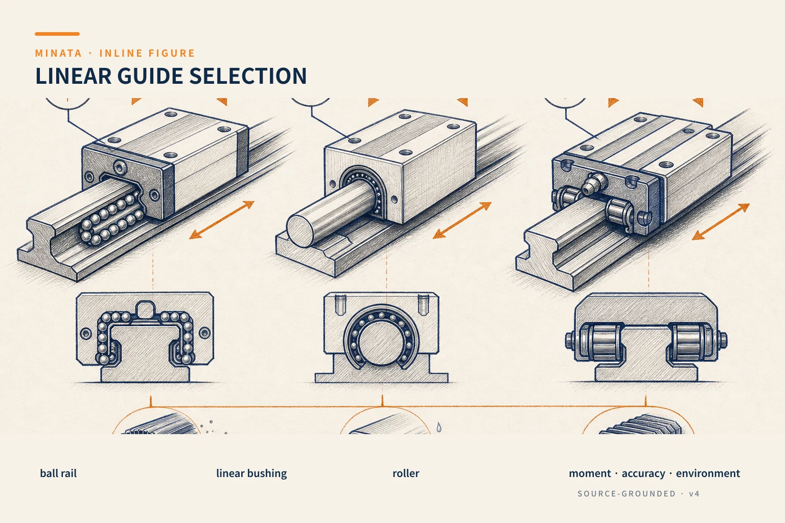
Load on a guide is not just "how many kilograms?"
A table carries a load of weight W, but the center of gravity usually does not sit right between the two blocks. When the table reaches out, when a cylinder pushes off-center, when a cable pulls off-center, or when accelerating, an overturning moment appears. That moment is shared by the rail, the block and the layout spacing. Two assemblies with the same weight can live very differently if one places four blocks far apart while the other places two blocks close together under a tall fixture.
Before choosing, draw the plan and side views of the table. Record the spacing of the two rails, the spacing between blocks on the same rail, the mass-center position, the acceleration force, the process force and the cable/tube pulling points. Then determine the moments about the three axes. The catalog usually publishes the rated load and allowable moment; use the maker's own reference frame rather than comparing individual numbers in isolation.
LM ball rail: prefer stiffness and a controlled layout
An LM ball rail consists of a rail with rolling grooves and a block recirculating balls or rollers. THK describes the LM Guide as a linear-motion guide element using rolling elements, comprising the block, the rail and recirculating balls. The rail–block structure carries load in several directions and is a familiar choice for machine slides, positioning axes, automated fixtures and mechanisms needing repeatable motion.
An LM rail's strength does not appear just because you bought a large block. The mounting surface must be flat and stiff enough, with a reference shoulder so the rail is mounted straight. If a thin aluminum face bends along the rail, the block can load unevenly. If the two rails are not parallel, the slide can be stiff to move, hot or wear early. Look at the flatness, parallelism, reference-face and tightening-torque requirements from the manufacturer in the assembly drawing.
An LM rail suits a moment load better than a single-shaft bushing because the contact and the rail geometry create an assembly that can resist overturning. Even so, you must still choose the number of rails and blocks. A single rail usually cannot resist rotation for a wide table on its own; four well-distributed blocks usually share the load better than two close-set blocks. When very high stiffness is needed, a roller guide/cross-roller or a heavy-load series may be the direction, but it brings a higher mounting-face machining requirement and cost.
Preload and the accuracy grade are also design parameters. Preload can reduce play and increase stiffness, while raising friction and requiring a better mounting face. Do not default to high preload for every mechanism. A lightly running table, a welded frame or an aluminum base may need a choice that tolerates the real mounting error more than one that chases the stiffest number in the catalog.
Linear bushing: simple when the architecture suits
A linear bushing, in the common sense, consists of a supported round shaft and a bushing with recirculating balls; there are also polymer/bronze plain-bushing types. This construction is familiar, easy to visualize and convenient when you must use long shafts or make a mechanism with open space. THK notes that a ball bushing has rolling elements in point contact with the shaft; its load capacity and moment resistance therefore differ from a profiled rail. When there is a moment, you usually need two or more shafts to stop the nut/table from rotating out of the direction of motion.
This is a detail to reflect into the BOM. If using two round shafts, the spacing between shafts, the support spacing and the stiffness of the table joining the two bushings decide the rotation resistance. Using a single round shaft for a table carrying an eccentric tool can create vibration or binding even when the vertical load is low. Do not let a guide shaft also carry the torque-transmission function if the assembly is not designed for that.
A bushing has the advantage in a simple mechanism, a sliding door, a covering table, a light jig and equipment that does not emphasize positioning. The material, seal and lubrication must be chosen by the environment: abrasive dust, wash-down water, cutting oil, a cleanroom or food all require review. An open shaft placed near welding/cutting dust needs a shielding and cleaning solution; just fitting a better bushing does not handle the source of the dirt.
Roller: a flexible architecture, but check the whole mechanism
A roller guide can be a V-wheel running on a V-rail, a roller following a profile, a cam follower or a wheel-guide assembly. It suits doors, transfers, mechanisms with a long travel path, open mechanisms that need to be easy to observe, and layouts unsuited to a profiled rail. When running on a profile, the designer can make the rail as part of the machine structure and place wheels on both sides to keep the direction of motion.
In return, the accuracy and life depend heavily on the rail path, the frame stiffness, the wheel bearing play, the mounting adjustment and the running-surface protection. A wheel with an eccentric adjuster helps set the contact, but must not be over-tightened, which raises friction. The wheel takes a local force on the rail; checking the rail material, hardness, wear and replaceability is necessary if the cycle is high.
A roller does not default to "handles dust well" either. Hard particles on the rail surface can create marks, noise and jumping. Its advantage is that the open mechanism is easy to clean and the wheel is easy to replace on some machines. For fine dust or oil splash, a better solution may be shielding, a wiper and a cleaning schedule rather than changing the guiding principle.
Choosing by accuracy and cycle
If the axis must repeat a position for a camera, robot or tool to work, the guide must be considered together with the transmission, the motor and the home sensor. A good rail does not compensate for an elastic timing belt, a coupling with play or a bending mounting face. #09 on motors and #11 on couplings help review the rest of the transmission chain.
If the mechanism only opens/closes a cover, more important factors may be dust, noise, replacement cost and jam resistance. Do not put a precision rail into a task where the frame, stops and transmission do not need it. Conversely, do not use two light round shafts for an eccentric fixture and then try to cure it by increasing the shaft diameter; the layout and guide type should be reviewed from the start.
The practical selection process
- Record the load, center of gravity, stroke, speed, acceleration and process-force direction.
- Lay out a preliminary number of rails/shafts/wheels and the spacing between them; compute the moment loads.
- Choose the principle: an LM rail for stiffness/positioning, a bushing for a suitable round-shaft architecture, a roller for a profile/flexible installation.
- Check the rated load, moment, life, speed, lubrication, seal and environmental limits of the model.
- Check the mounting face, frame stiffness, alignment reference and the install/remove maintainability.
- Test with a representative load, observing the pulling force, noise, heat and wear marks before replicating the machine.
Common mistakes
- Choosing a rail by the vertical load and dropping the moment from the table reaching out.
- Mounting two rails on a thin base with no reference face to align them parallel.
- Using a single shaft/bushing for a table carrying an eccentric tool.
- Calling a roller "dust-resistant" without designing rail-surface cleaning.
- Forgetting the lubrication, seal or how to replace the block/bushing after the machine is enclosed.
Installation details decide the smoothness of the whole assembly
The rail and block must be installed in a referenced sequence. For two rails, you usually mount the reference rail against a machined shoulder, then bring the other rail parallel with a dial gauge or the maker's procedure; do not force the block to pull the two rails into position after the screws are fully tightened. Recheck the pulling force by hand or the motor current at several stroke positions, because a parallelism error may show only at one end of the rail.
A long rail needs consideration of rail joining, the joint position, the block's running direction through the joint and the base straightness. For a fast-running table, the drag cables and air tubes are a dynamic load: a too-stiff chain or an off-pulled hose can create a continuous lateral force. Put the cable carrier, anchor point and bend radius into the guide layout from the start. For a vertical assembly, add a suitable anti-drop or braking mechanism; a guide rail does not hold the load by itself when the motor power is lost.
The maintenance plan should have accessible lubrication points, removable covers and inspection criteria such as abnormal noise, rail scratches, increased running force or table play. If you cannot lubricate/inspect after the machine is enclosed, the catalog life is no longer a realistic assumption. Record these criteria in the mechanism acceptance.
Quick selection checklist
- [ ] Have you drawn the center-of-gravity position, process force and moment on the slide table?
- [ ] Do you need high stiffness/accuracy and overturning resistance? Yes → prefer an LM ball rail with a suitable rail/block layout.
- [ ] A simple round-shaft mechanism, moderate load/moment, and two shafts to resist rotation? Yes → consider a linear bushing.
- [ ] Do you need a profile-following path or an open, easy-to-maintain mechanism? Yes → consider a roller and check the rail surface.
- [ ] Have you checked the mounting face, lubrication, seal, environment and alignment method?
MINATA can work with the machine team to review the moment load, rail layout and the mounting-face machining capability before locking the guide model. Talk to the Engineering & Manufacturing team.
References
View all MINATA technical articles