Device Selection #19: FRL Air Preparation — By Flow and Cleanliness
An FRL unit should be chosen from the air demand at the point of use: simultaneous flow, working pressure, cleanliness level, condensate amount, the mounting environment and how to drain/maintain it. The filter, regulator and lubricator have different tasks; assembling all three parts does not automatically make the air system suitable. Start with a diagram from the air source to each machine branch, then determine which part needs filtering, which needs regulating and which really may be lubricated.
Quick comparison
| Element | Main function | To determine when choosing | Common mistake |
|---|
| Filter/Water separator | Removes particles and condensate to the device grade | Filtration grade, flow, bowl, drain, pressure drop | Choosing by thread size then ignoring the filtration level and flow |
| Regulator | Reduces and maintains the regulated pressure for a branch | Regulation range, flow, stability, gauge | Setting one common regulator for different pressure needs |
| Filter-regulator | Combines filtering and regulating at the point of use | The same filter/regulator conditions | Mounting in the wrong order or with no drain plan |
| Lubricator | Delivers a measured amount of oil into the air for devices that require it | The device's real requirement, oil, mounting position | Using it by default for every circuit so oil goes throughout the system |
| Lockout/exhaust valve, soft-start, sensor | Isolate, exhaust pressure, controlled pressure build-up, monitoring | Risk review, operating sequence, maintenance | Treating the FRL as a substitute for lockout and the safety function |
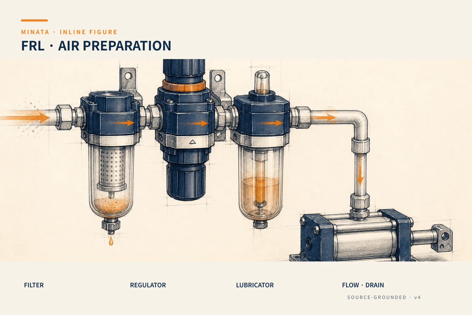
An FRL is part of the pneumatic architecture
An FRL is usually named from the three words Filter–Regulator–Lubricator, but a real air station may also have a lockout valve, exhaust valve, soft-start, water separator, fine filter, pressure gauge, pressure sensor, manifold and local regulation branch. Their order and number depend on the air source, humidity, the cleanliness needed at the load, the device type and the maintenance requirement. So the correct choice is a functional diagram with parameters, not a combo code reused for every machine.
Draw the air path from the factory's compressor/dryer to the machine and to the points of use: directional valve, cylinder, vacuum ejector, blower, air tool or measuring device. Along that path, record the tube size, length, source pressure, the pressure required at the point of use, the estimated flow and the number of loads operating at once. A cell using many cylinders may need a peak flow very different from the average flow; an ejector needs enough supply pressure right at suction; an air tool can create a large variable flow. The FRL must meet this defined unfavorable condition.
Separate the cleanliness requirement before choosing the filtration grade
"Clean air" is not enough to order a filter. You must ask what the downstream device is sensitive to: particles, liquid water, oil aerosol, oil vapor, or microorganisms/special material conditions. The datasheet of the valve, cylinder, vacuum generator, air tool or process device is where the requirement is defined. If the branches have different requirements, one common treatment stage at the machine inlet may be insufficient, or excessive for the whole flow.
A standard filter usually serves particle and condensate separation at the level the series states; a fine filter or mist separator has a different application. Do not replace one filtration grade with another just because the thread is the same. Cross-check the efficiency, the particle size/contaminant type the maker states, the nominal flow under the test condition and the pressure drop both when the element is new and when it is near replacement. In an oily/aerosol environment, choosing the wrong filtration chain can affect a sensor, seal or product surface.
Condensate is an operating element, not a footnote. The bowl must be visible/inspectable, allow removing and replacing the element, and the drain method must suit the mounting position. A manual drain requires an inspection schedule; a semi-auto/auto drain has its own operating conditions and needs a properly handled drain line. Do not route condensate where it causes slipping, corrosion or contamination. Festo notes that the soft-start position must avoid being placed upstream of a normally-open/semi-automatic drain in a way that lets air continuously escape through the drain; the device order must be read per the documentation of the exact configuration.
Choose the regulator from the pressure at the load, not from the pressure on the receiver
A regulator reduces and holds the pressure for a usage zone within its condition limits. When choosing, you must know the lowest source pressure, the set-pressure range needed, the peak flow, the flow varying by cycle, the desired stability and the real pressure at the load. The adjustment range must cover the setpoint with a reasonable margin; choosing a regulator with a high range but hard to control well at low pressure may not suit a low-force mechanism.
The pressure at the regulator port is not the pressure at the cylinder or ejector. The valve, tube, elbow, fitting, filter element and silencer all lose pressure. If a cylinder lacks force when the machine runs fast, measure the pressure near the cylinder/valve during the real cycle rather than immediately raising the setpoint. Raising the pressure to compensate for one bottleneck can make another mechanism run harder, impact at the end of stroke or exceed the device's limit. After measuring, address the real cause: a dirty element, an undersized regulator, a too-small tube, an overloaded manifold or an underestimated air demand.
You should separate regulation zones when the loads need different pressures, when there is a load sensitive to pressure fluctuation, or when one branch has a peak flow that affects the other. Each zone should be named on the diagram, have a gauge/sensor at a useful position and a clear pressure limit. For a clamp, lifting or vacuum assembly, link the pressure level to the computed force/suction requirement, not adjusting it by the operator's feel.
Flow and pressure drop: the thread is only a small part
The thread or port size is not enough to conclude the FRL size. Two units both G1/4 can have a different nominal flow, bowl construction and pressure drop. Festo publishes MS combinations with different standard nominal-flow ranges by size and configuration, illustrating that the same filter-regulator-lubricator function must still be sized by the specific model. The specs to read are the flow of the exact configuration, the pressure condition, the connection size, the temperature range, the regulation range and the drain type.
Build a demand table by each mechanism: the volume/consumption per cycle, the number of cycles, the running time, the simultaneity factor and the pressure requirement. For a cylinder, the bore/stroke/pressure and cycle are the inputs. For a vacuum ejector, look at the supply pressure and compressed-air flow of the exact nozzle. For a blow-off, the opening time and orifice can create a large peak. Aggregate by the worst-case scenario, then cross-check the maker's characteristic curve/sizing guidance. Theoretical figures should be confirmed by testing when the machine has sensitive loads.
The path from the FRL to the load must also be computed. A large FRL at the machine inlet does not help much if the branch after it is long, the tube small or there are many elbows. Conversely, upsizing the whole unit because one branch is choked can waste space and not fully solve it. The goal is to distribute enough pressure/flow at each point of use and be easy to maintain, not the largest device size.
Use a lubricator only when the device really requires it
A lubricator supplies an adjustable amount of oil into the air. It is useful for a device that needs lubrication per the manufacturer's guidance, with the correct oil type and a controlled mounting position. However, modern pneumatic devices usually already have suitable grease lubrication; Festo notes that a lubricator is usually not needed for a modern system and oil can wash out the grease in components, so once oil is supplied it must be maintained continuously. Therefore, do not add a lubricator as a default component of the BOM.
If a branch must be lubricated, place it so the oil only reaches the device that needs it. Festo recommends, where possible, placing the lubricator near the consuming device so as not to carry oil through the whole system; do not place it before a fine/micro filter or a flow sensor. Separate this branch from circuits requiring oil-free air, vacuum, sensitive sensors or a process with a clean requirement. State the oil type the maker allows, the supply level, the refill position, the anti-overfill measure and how to detect it running out of oil.
Bowl, drain, layout and the mounting environment
A plastic or metal bowl, guard, bowl size, level indication, temperature range and chemical resistance are all part of the choice. Festo notes that some MS units have a metal or guarded polycarbonate bowl option; you cannot infer that one bowl type suits every position. If there is a risk of impact, light, solvent, heat or a requirement to see the water level, use the option the manufacturer allows and arrange a suitable shield/guard.
Mount the FRL in the orientation and position the catalog specifies so the water-separation/drain function works correctly. Leave a gap below the bowl to remove the element and place an observable drain line. Do not cover the gauge with the machine frame, do not leave the drain behind a closed panel, do not let the regulator knob touch a tube. The airflow direction, the IN/OUT labels, the auxiliary ports and the mounting-bracket position must be shown on the assembly drawing. In a vibrating environment, also check the bracket, the sensor connector and the risk of a loose fitting.
FRL, energy isolation and machine start-up
An FRL makes the air condition stable but is not by default a lockout/tagout device or a safety exhaust. During maintenance, you need a way to isolate the energy source and exhaust the pressure per the machine's procedure. On restart, a machine with a movable mechanism may need a controlled pressure build-up, a position/guard check, and only then allow the cycle. A lockout valve, exhaust valve, soft-start and pressure sensor must be determined from the risk assessment and the operating logic, not just placed by habit.
List the situations of power loss, pressure drop, air cut, reset after E-stop and filter replacement. Some circuits require exhausting everything; some need to maintain a separate zone by a controlled design. This decision relates directly to the cylinder, directional valve and mechanical load. The article choosing a 2, 3 or 5-port solenoid valve and the article choosing an air cylinder are two connection points to review with the air diagram.
Plan maintenance from the day you choose the device
Do not wait for the bowl to fill or the cylinder to run slow before thinking about maintenance. The specification must record the element part number, spare quantity, how to check pressure, the drain-inspection schedule, the element-replacement criterion and the responsible person. The schedule should not be based only on date if the environment and flow change; the differential pressure, declining flow or the number of operating hours may be a more suitable signal depending on the system. Follow the maker's recommendation for each element.
Record a baseline at commissioning: source pressure, set pressure, pressure at the load under a heavy cycle, bowl state, model/filter grade and the regulator setting. When there is a fault, comparing with the baseline helps trace the cause faster than randomly replacing parts. Keep a clean, sealed spare element with the correct code; fitting the wrong filter grade can make the system fail the requirement in a way hard to notice by eye.
The FRL selection process
- List each point of use, the required pressure, the cleanliness level and the simultaneous-flow scenario.
- Determine the source condition: the lowest pressure, the humidity/oil/particles, the dryer and the upstream piping.
- Choose the filter/water separator/fine stage by the downstream requirement; lock the grade, bowl and drain.
- Choose the regulator by the pressure range and real flow; separate zones when the loads or required pressures differ.
- Add a lubricator only for a branch the downstream manufacturer requires, with the defined oil and position.
- Check the pressure drop of the whole path, the mounting position, the element-replacement space, the drain and the gauge.
- Determine the isolation/exhaust/soft-start valves from the risk review, test and record the operating baseline.
Checklist before locking the BOM
- [ ] Do you have the table of peak flow, number of simultaneous loads and pressure at each point of use?
- [ ] Does the filtration grade match the contaminant the downstream device needs controlled?
- [ ] Are the filter element, bowl and drain chosen by the exact model, environment and maintenance plan?
- [ ] Does the regulator have a suitable setpoint range, flow and stability at the real load?
- [ ] Have you checked the pressure drop through the FRL, tube, fitting, valve and silencer under the worst cycle?
- [ ] Is the lubricator really required by the device and separated from the branches needing clean air?
- [ ] Are the lockout/pressure-exhaust/soft-start positions and element replacement shown in the layout and procedure?
MINATA can work with the machine team to review the air demand, the FRL diagram, the maintenance position and the real pressure data before locking the BOM. Talk to the Engineering & Manufacturing team.
References
- MISUMI, Factory Automation Catalog 2018, Cylinders / Valves / Air preparation chapter; cross-checked against MINATA's internal catalog on 2026-08-23.
- Festo, Air preparation white paper, referencing the lubricator position, soft-start and operating notes.
- Festo, Filter regulators, referencing the combined filter–regulator function and sizing.
- Festo, MS series service-unit combinations, an example of flow ranges, ports and FRL configurations by model.
View all MINATA technical articles