Device Selection #18: Air Cylinders — Bore and Mounting by Force and Stroke
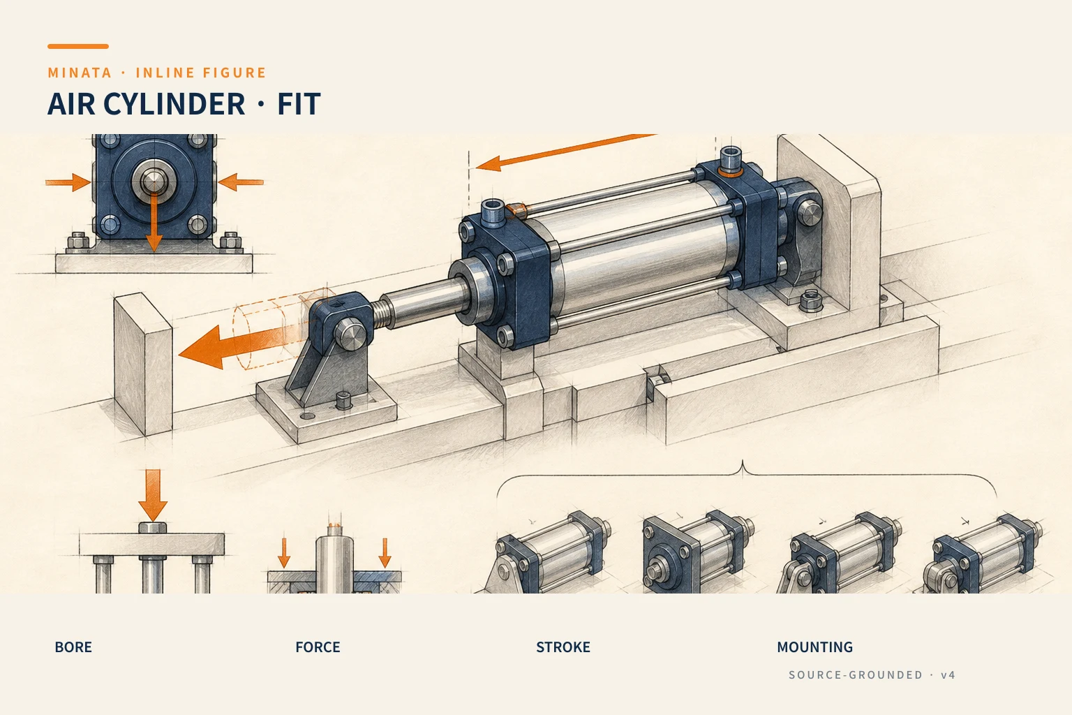
Choose an air cylinder by computing the force needed at the mechanism under an unfavorable condition, then checking the stroke, side load, speed, mounting type and cushioning. A larger bore only increases the theoretical force; it does not by itself handle an eccentric load, a bent rod, an end-of-stroke impact or the risk of the mechanism dropping when air is lost. The correct choice must describe both the normal motion and the state on power loss, pressure loss and maintenance.
Quick comparison
| Cylinder/mechanism type | When suitable | What to check first | Risk if chosen wrong |
|---|
| Standard cylinder with rod | Push/pull along one axis, simple mounting | Advance/retract force, stroke, rod load, mounting type | Rod side-load, impact at end of stroke |
| Compact cylinder | Short vertical space, limited stroke | Mounting space, external guide, sensor | Using the compact body to take a moment instead of a guide |
| Guided cylinder | Slide table or a load with a moment | Load, mass center, allowable moment | The guide overloaded even when the cylinder force is enough |
| Rodless/slider cylinder | Long stroke, wanting to reduce total length | Sealing, guide, load and protection | Off-center load or a hard-to-detect air leak |
| Single-acting cylinder | Working in one direction, returned by spring/load | Working-direction force, return force, air-loss state | Incomplete return or an unsafe stopping state |
Start from the motion at the mechanism
Draw the object to move, the force-application point, the direction of motion, the useful stroke, the direction of gravity and the guide points. If the mechanism clamps, the required force is at the clamp jaw, not just at the rod end. If it is a slide table, the load may sit eccentric to the guide center. If it is a lifting mechanism, the payload always exists in the falling direction even when the cylinder is stopped. This diagram is the input to choose the cylinder, not an illustration step after choosing.
Record the cycle clearly: where it starts, how far it advances/retracts, the accel–decel time, the hold time, the number per minute and the number of stations running at once. Those figures decide the flow, valve size, air consumption and the heat generated through the silencer. Also record the material/environment: welding dust, cutting oil, water wash, heat, chemicals, a food area or a clean requirement. The seal, rod material, grease and sensor must be chosen under those same conditions.
Computing force: distinguish theoretical force from useful force
The theoretical force on the rodless side is computed from the applied pressure times the piston area. On the rod side, the effective area is smaller because you must subtract the rod's cross-section. So at the same pressure, the pull force of a double-acting cylinder is usually smaller than the push force. The formula is the starting point to compare bore sizes; only the catalog of the exact series provides the force, pressure range and application conditions to lock the model.
The design force must include the guide friction, spring force, the gravity component along the direction of motion, the process force such as pressing or separating, and the acceleration effect. For a horizontal motion with slide rails, the friction depends on the guide type, lubrication, cleanliness and load. For a vertical motion, taking just the mass times gravity is not enough if there is acceleration, a counterbalance or a force-transmission mechanism. SMC also notes that cylinder figures are a model-selection guide and the resisting force changes with the operating pressure; so do not replace the calculation with a maximum force value in a table.
The safety factor does not have a fixed number for every machine. It must reflect the variability of friction, load, air leak, lowest pressure, mounting error and the consequence of not reaching the force. State the assumptions clearly in the calculation sheet: the pressure at the cylinder port, the resisting force computed, horizontal/vertical/inclined motion, the guide mechanism, and the unfavorable condition. When the assumptions change, for example adding a heavier fixture, the calculation must be reviewed.
Bore and stroke: two parameters that always go together
After you have the minimum force, choose the bore within the catalog range and recheck the force at the lowest working pressure. Do not just take the compressor pressure or the value on the main regulator as the pressure at the cylinder. The pressure can drop through the FRL, valve, tube, fitting and when many mechanisms operate at once. The article choosing FRL air preparation helps check this upstream part.
The nominal stroke must cover the necessary motion plus a reasonable adjustment, but should not be extended just "to be safe." A long stroke increases the body length, the air volume per cycle, the response time and the risk of the rod sagging/buckling under compression. If you need an intermediate position or several stopping points, review the transmission mechanism, guide and sensor rather than expecting a long-stroke cylinder to solve positioning by itself. A mechanical end stop, adjustment shims and the fixture tolerance must be shown in the layout.
For a long stroke, also check the rod buckling limit per the exact catalog. The compressive force, rod diameter, free length and the mounting type at both ends change the buckling capacity. A cylinder with a bore giving enough force may still be unsuitable because the rod is slender or the mounting makes the free length large. Do not use another series' numbers to conclude; the maker determines the limit by the construction, guide and specific mounting.
The mounting type decides the force path
The mounting type is not just a bought-in accessory. A front flange, rear flange, foot mount, clevis, trunnion or direct mount changes how the force and moment travel from the cylinder into the machine frame. Ask: where is the cylinder held; what joint connects the rod end; does the mechanism rotate about a joint; is the frame stiff enough; and does the mounting error accumulate into the seal or into which guide.
A rigid two-end mount suits when the motion axis is well aligned. A clevis or rod-end joint allows compensating part of the angular error in a rotating mechanism, but does not turn the cylinder into a lateral-load element. A trunnion lets the cylinder rotate with the mechanism, needing a check of the sweep space and the gravity direction. For every type, the maintenance access for the pin, nut, sensor band and air port must be left on the drawing.
A common mistake is hanging an external load at the rod end and letting the piston/rod take the moment. The rod is designed to prioritize axial force transmission, while the lateral load and moment should go through a linear guide, slide table or a separate guiding mechanism. If space forces the load near the rod end, the distance from the guide to the force point and the mass center must be put into the calculation, not just written as "light load."
When you need a guided cylinder
A guided cylinder or slide table suits when the load must keep its direction, has an off-axis process force, or the fixture creates a moment. The SMC catalog for a guided cylinder requires checking the load, mass center and allowable moment; for example a tilted slide table must compute the moment from the load, not just the axial force. This is a good principle for every maker: read the load/moment chart of the exact model, by the allowed guide type and mounting.
Choose the guide by the load, not just by the cylinder bore. Look at the three moments about the axes, the mass-center position throughout the whole stroke, external forces such as pressing/pushing, and the acceleration. Check the open/closed state too, because an arm or fixture can change the lever arm. If the load rocks at the end of stroke, increasing the bore will not fix the guide part; it may even make the impact worse because the mechanism has more force and speed.
Speed, cushioning and air consumption
The cylinder speed is the result of the flow, chamber volume, load, pressure and the exhaust/supply regulation. The directional valve, speed controller, tube, fitting, filter and silencer all take part. Use a speed controller to adjust the speed after the circuit has a suitable flow capacity; screwing the throttle too closed to mask an undersized valve/tube usually creates an unstable motion and a hard-to-repeat cycle time. See the article choosing a 2, 3 or 5-port solenoid valve to lock the directional-circuit part.
The end of stroke is where you must look at the kinetic energy, moving mass and frequency. Integrated air cushioning can suit within the load/speed range the catalog allows. For a large load, high speed or a precise-stop requirement, use a shock absorber or a suitable stop mechanism, and check the reaction force transmitted into the frame. Do not adjust the cushioning before fixing the main variables; set the starting point per the maker's guidance, test from slow to the target condition and record the setting.
Air consumption affects the source size, FRL and operating cost. When choosing a bore larger than needed, each cycle charges/exhausts more air and the valve/tube may also need to be larger. The cylinder data must be used with the operating pressure, stroke, number of cycles, and the number of actuators running at once to estimate the total demand. The goal is enough force and a stable cycle, not a maximum bore.
Position sensors and mounting clearance
Many cylinders use a magnetic piston and a groove/band-mounted sensor to detect near the two ends of stroke. This sensor does not replace a mechanical end stop and does not by itself prove the slide table or fixture has reached the correct position if there is still play. Choose the sensor by the cylinder type, slot type, PNP/NPN output, supply, connector, temperature range and environment. The article choosing a cylinder position sensor presents in more detail how to choose the sensor.
On the layout, leave space for the sensor, the cable bend radius, the cable clamp and the adjustment handling. The sensor label should match the I/O diagram and the mechanical position. In commissioning, check both ends of stroke at low pressure and at rated pressure, also with the real load mounted. If the cycle time uses a sensor signal as the condition for the next step, consider the PLC/filter debounce time and the possibility that the mechanical part is not yet settled when the sensor just turns ON.
Air loss, power loss and a vertical load
Compressed air can be lost due to a machine stop, lockout, source pressure drop or a broken tube. For a lifting cylinder, you must decide whether the load may lower, must be held, or must be supported by another mechanism. A 5/3 center-closed valve is not the general answer because there is still leakage, air compressibility, the load configuration and the safety requirement. You may need a mechanical brake, rod lock, counterbalance, a mechanical pin, a stop block or a safety solution that has passed a risk assessment.
Record the desired situation in the specification: loss of 24 VDC, loss of the air source, E-stop, reset and maintenance. Also design the pressure-exhaust/lockout point so maintenance does not rely on the pressure remaining in the cylinder. This work relates to the whole machine's risk assessment; the integrator must lock the safety architecture before accepting a cylinder model.
A re-checkable selection process
- Build a diagram of the mechanism, load, stroke, cycle, gravity direction and environment.
- Compute the required force at low pressure and unfavorable load/friction; distinguish advance and retract force.
- Choose the bore, rod and stroke from the exact series catalog; check the force, buckling, pressure range and temperature.
- Choose the mounting type and joint by the force path; add a guide when there is a lateral load or moment.
- Check the speed, valve, tube, speed controller, cushioning/shock absorber and air consumption.
- Choose the sensor/cable, leave mounting space and check the power-loss/air-loss state.
- Test with the real load, the lowest pressure, the highest cycle and save the result in the machine file.
Mistakes to avoid
- Choosing the bore from an on-hand list and then trying to justify the force.
- Using the piston push force to conclude for the rod-side pull direction.
- Letting the rod take a side-load/moment instead of a linear guide.
- Looking only at the static load while dropping the acceleration and the end-of-stroke impact.
- Choosing a compact cylinder for its size but not checking the space for the sensor, port and joint.
- Treating the cushioning as an emergency-stop brake or the valve as a load-holding solution on air loss.
Checklist before locking the BOM
- [ ] Do you have the required force in the advance/retract direction, the lowest pressure and the unfavorable load condition?
- [ ] Have the bore, rod, stroke and buckling limit been cross-checked against the exact series catalog?
- [ ] Do the mounting type, rod-end joint and load path avoid a side-load on the rod?
- [ ] Have the load, mass center and moment been checked with a guide/slide when needed?
- [ ] Do the valve, tube, throttle, cushioning and shock absorber reach the required speed/cycle?
- [ ] Are the sensor, cable and maintenance space in the layout?
- [ ] Do power loss, air loss, E-stop and lockout have an assessed behavior?
MINATA can work with the machine team to review the calculation sheet, mechanical layout, air circuit and a real-load test before locking the BOM. Talk to the Engineering & Manufacturing team.
References
View all MINATA technical articles