Device Selection #21: Aluminum Extrusion — Series 20, 30, 40 or 50 by Load
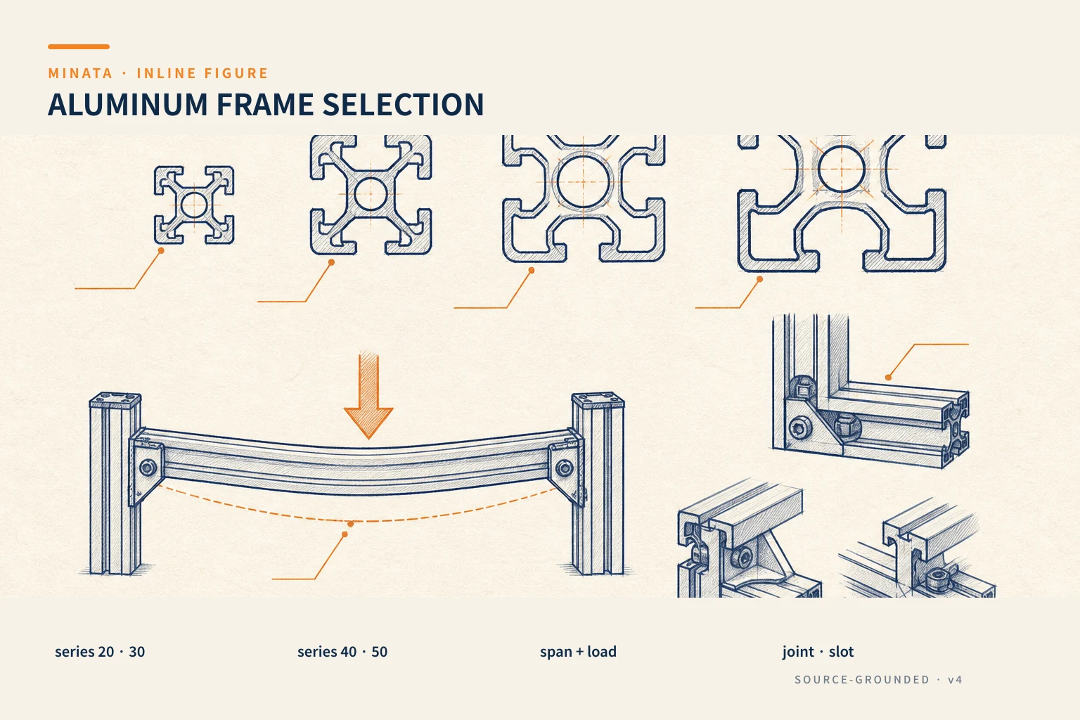
Choose aluminum extrusion from the load, free span, load-application point, allowable deflection, connection and the components to be mounted on the frame. "Series 20, 30, 40, 50" is only each maker's profile-system convention; the same series name does not guarantee the same T-slot, moment of inertia, nut type or accessories. Lock one catalog system first, then check the profile and joint by that system's exact data.
Quick comparison
| Common profile size/system | When suitable | What to check | Warning |
|---|
| Small series 20/25 | Sensor bracket, light cover, small fixture | Short span, panel, compatible thread/nut | Do not use by feel for a machine leg or a long span |
| Medium series 30/40 | Medium machine frame, work table, guard | Beam deflection, concentrated load, bracket | The outer width does not tell the stiffness in both axes |
| Large series 45/50 and up | Base frame, heavy load, tall column | Moment, torsion, foot, connection | A large profile is still weak if the joint/gusset is wrong |
| Closed/special profile | Needs routing, cleanability, panel/gasket | Shape, nut-install access, accessories | Do not switch to a "nearly similar" profile from another maker |
Start from the load and the frame geometry
Before choosing a catalog, draw the frame by its real load-bearing bars: vertical legs, horizontal beams, braces, doors, panels, screens, robots, conveyors, electrical trays and the maintenance load. Record the free length of each bar, whether the load is distributed or concentrated, the force direction, the hanging point and the center-of-gravity position. A frame for a thin cover is fundamentally different from a frame supporting a linear axis with an acceleration load or a work table with a person leaning on it.
The static load is only one part. A moving mechanism creates vibration, a reversal force, a moment at the support and a shock when stopping. An opening/closing door, a pulled-out table, a cylinder, a pulling cable or a person leaning on the frame can all be a load case. List at least these states: normal operation, maximum load, door open, maintenance and transport if the machine is moved. These states help avoid building a nice frame but having to add a reinforcing plate after the trial run.
The deflection must be determined from the task. A cover frame can accept a different displacement from a frame holding a camera, sensor, rail or a precise mounting surface. Saying "the frame must be stiff" is not enough for the designer and supplier. Record the measurement position, the measurement direction and the limit by function: mechanical clearance, sensor alignment, table flatness, or the guard gap. The maker's profile data provides the moment of inertia and the section modulus to check for the specific profile.
A series is a mechanical system, not just a cross-section size
Manufacturers name their profile system by the module grid, slot size, nominal size or a commercial designation. MISUMI 2018 groups profiles into series 5, 6 and 8 with many different cross-sections; within each group there are also specific nuts, brackets, joints and plates. Bosch Rexroth also publishes profiles with the slot spec, area, moment of inertia, section modulus and mass per part number. So "40x40" is not a complete specification.
Before creating the BOM, lock the maker/system, the profile code, slot size, cross-section shape, surface type, accessories, nut, bolt and tooling. A T-nut from another system may not enter the slot, may fit but not hold correctly, or may block the cover strip. A hidden connector has a different bar-end machining requirement from an angle bracket; this affects the lead time, the cutting/tapping tools and the ability to change it on site.
Do not mix profiles, brackets and nuts across systems without confirming compatibility by drawing and load. "The same 8 mm slot" does not prove the slot-neck shape, tolerance or holding force are the same. For a machine needing maintenance over many years, keeping a clear accessory system is worth more than saving a small fraction of the cost per bar.
Check the beam by the bending direction and span
A rectangular profile has different stiffness about the two axes. Rotating the profile 90 degrees can significantly change the moment of inertia in the load direction. When a beam carries a vertical load, placing the tall side in the direction that needs to resist deflection is usually more effective than increasing the horizontal width, but you must check the mounting space, joint and lateral load too. Do not decide only from a catalog photo or the front-face dimension.
For a beam, determine the support condition: two-end supported, cantilever, or a soft joint near the support. The ideal beam formula is a screening step, because the real frame is also affected by the bracket stiffness, bolt preload, joint clearance and the side frame. After a preliminary profile calculation, check the connection and run a load test when the frame holds a sensitive element. If the design uses a rail or a precise measuring sensor, consider the thermal expansion and the locating method, not just the static bending.
A closed-form or ribbed profile can perform better for some load/torsion directions, but only with the maker's spec. Aluminum extrusion is a modular system: increasing stiffness can also come from reducing the span, adding a cross member, adding a diagonal brace, a panel acting as a shear panel, or changing the load path. These solutions must be assessed so they do not lose access for the cable, door or maintenance area.
The connection is where the frame really works
A right angle in CAD does not create stiffness by itself. An external bracket is easy to build and easy to check but takes space; a hidden connector creates a clean surface but usually requires machining/profile prep; a large gusset supports better anti-racking on a tall frame but can obstruct a panel. Choose the joint type by the force/moment, the number of disassemblies, the assembly tools, the aesthetics when needed, and the space for a cable tray or panel.
Determine which joint the force passes through. A beam supporting a mid-load transmits shear and moment to the two ends; a column foot takes compression, lateral force and can suffer pull-out when the frame vibrates. If a bolt only clamps a thin face of the profile or the bracket is too small, increasing the beam profile may not improve the frame. Record the torque, fastener type, nut, washer and access position on the assembly drawing; do not let the assembler choose from an accessory bin.
A tall frame or one with a large door must consider the racking capability. Just four bars forming a rectangle can deform into a parallelogram under a lateral force without a suitable gusset, diagonal, panel or rigid connection. Check the condition when the machine opens a door, moves, or has a laterally acting mechanism. Also check the foot/caster system: the element under the frame chosen in #22 on casters and adjusters decides how the load goes down to the floor.
The T-slot and accessories are part of the decision
A T-slot creates the advantage of fast install/repair, but must be planned. Mark right on the layout which face is used to hang the panel, cable duct, sensor, door hinge, guard mesh, tablet arm, leveling foot and tray. If you use up the outward-facing slots with brackets, covers or panels, adding equipment later will be much harder. Keeping some usable faces/slots is an engineering choice, not a waste.
Choose the nut by the install method and position. A drop-in nut suits when the profile is still open; a post-assembly nut is useful when you need to add an accessory later; a spring/ball type holds position conveniently for vertical mounting but still needs the correct slot. The stop set, end cap, cover strip, panel fastener, hinge and handle should be in the BOM from the start. They affect safety, cleanability, the user's handling and the finishing time.
Check whether a cut profile end needs an end cap, whether the cut surface creates a sharp edge, and how the grounding/wiring points are handled per the machine's electrical design. Aluminum profile does not replace a designed bonding/grounding architecture; this article only handles the structural choice, not a basic electrical guide.
Panel, guard and the interface with other mechanisms
The frame is usually the backbone for panels and guards. A polycarbonate sheet, sheet metal, mesh, gasket, hinge and lock create a load as well as decide the tightness/safety. Choosing the profile before knowing the panel thickness, the clamping method and the removal requirement easily leads to adding scattered brackets. Lock the outline of the panels, doors, opening positions, cable slots and the need for a gasket before cutting the bars.
If the profile is part of a safety fence, choosing the frame must go together with the risk analysis, the mesh hole size, the distance to the hazard, the door and the interlock. The profile only creates the frame; it does not prove the whole guard meets the requirement. The article safety peripherals: lights, guards and E-stop states the boundary between these components.
For a measuring/vision device, avoid using the common guard frame as the datum for a critical sensor if it has a door or a vibrating panel. Separate the measuring bracket/beam from the frame part carrying the operating load when needed. For a robot/conveyor, check the interface plate and bolt pattern; do not assume the profile can directly take the device's dynamic load without a plate/gusset and a calculation.
Life-cycle cost and the ability to change
A profile is usually chosen for the speed of machining/assembly and the ability to change. Keep that advantage in the design: use standard lengths when reasonable, repeat the module, reduce the number of bracket types, use a clear cut list, and label the bars and fastener bags by subassembly. A wrong cut, a wrong tap or mixed nuts usually costs more time than the small difference between two cross-sections.
Assess the total cost including the profile, cut/tap, connector, plate, bracket, nut, fastener, panel, door hardware, foot, transport and assembly hours. A small profile needing many braces/joints may not be cheaper than a larger profile. Conversely, choosing the largest series for every bar makes the BOM heavy and hard to reuse. Choose by each frame member after knowing the load path.
When changing the layout later, you need to know the profile code, length, joint position and the original design load. The handover should include the assembly drawing, cut list, hardware BOM, torque/fastener note, the points that must not be drilled/cut, and photos of the frame after assembly. This is the data that helps adjust the machine safely rather than adding bars by experience.
The data-driven selection process
- Draw the frame, load, span, support points, mounted mechanisms and the operating/maintenance load cases.
- Lock one maker's profile system; take the drawing and section data of each intended profile.
- Check the force, deflection, profile orientation, torsion and the frame's racking capability; add braces or change the geometry when needed.
- Choose the joint, nut, bolt, bracket, plate, end cap and access by the load path and the install method.
- Lock the panel, door, cable routing, guard interface, foot/caster and maintenance space.
- Build a cut list/BOM by the correct system's profile code, mock up a subassembly, then lock the batch cutting.
Common selection mistakes
- Calling "series 40" a sufficient specification without the maker, slot and profile code.
- Choosing a larger profile but not checking the joint, foot or the lateral force causing racking.
- Checking the beam in one direction then rotating the profile differently on assembly.
- Choosing an angle bracket after using up the slots for the panel/cable duct.
- Hanging a dynamic device on a cover frame without checking the load path and plate.
- Treating the profile frame as a complete safety guard without choosing the mesh, door, interlock and distance.
Checklist before locking the BOM
- [ ] Do you have the load cases, free span, load-application points and the deflection limit by function?
- [ ] Are the maker/system, slot size, profile code, nut and bracket from the same compatible catalog?
- [ ] Have the stiffness in the correct profile orientation, the torsion and the anti-racking been checked?
- [ ] Do the joint, gusset, plate, fastener and foot have a clear load path?
- [ ] Are the panel, door, guard, cable routing and maintenance access on the layout?
- [ ] Are the cut list, hardware BOM, assembly drawing and torque requirement enough to hand over?
MINATA can work with the machine team to review the load path, section data, frame layout and BOM before batch-cutting the profile. Talk to the Engineering & Manufacturing team.
References
View all MINATA technical articles