Device Selection #24: LED Lights, Safety Guards and Emergency Stops by Machine Risk
An LED light communicates a state; a guard limits access to a hazard; an emergency stop activates an emergency-stop function. These three groups must be chosen from the risk assessment of the exact machine, the operator's position and the designed stop sequence. Do not use an indicator light to replace physical protection, do not consider a single guard enough if there is still uncontrolled access, and do not place an E-stop just because there is empty space on the panel.
Quick comparison
| Component | Main task | Question to answer | Does not by itself replace |
|---|
| Tower/status LED light | Communicate visible operating information | Who needs to see it, from where, which states must be distinguished? | Guard, interlock, E-stop or fault-handling alarm |
| Fence, panel, guard door | Prevent/limit access to a mechanical hazard | Where is the hazard, what is the distance/surface/access? | The risk assessment, interlock and safety logic when needed |
| Door/guard interlock | Detect/control the guard-open state by design | When a door opens, which function must stop and how does it reset? | The physical strength of the guard or a general E-stop |
| Emergency stop button | Activate the emergency-stop function by the machine design | Who needs to operate it, which energy/motion does it stop? | Isolation/lockout, a brake, a guard or a safe restart |
| HMI/buzzer/label | Guide, report faults, recognize an action | Is the information clear and what is the next action? | An engineering risk-reduction measure |
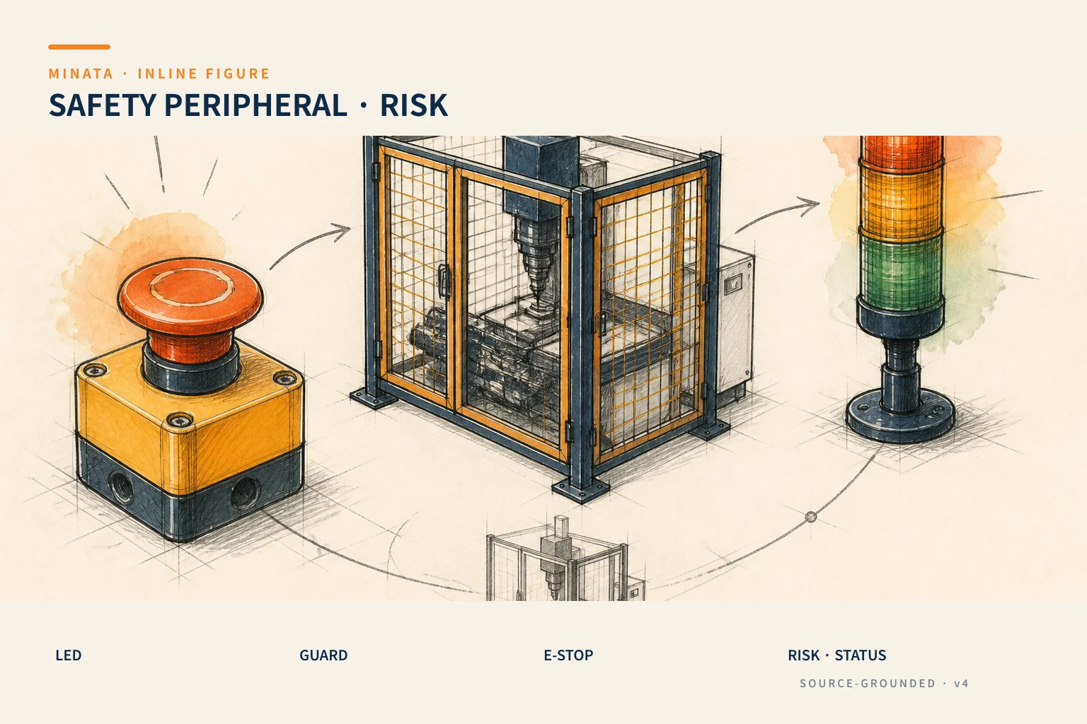
The starting point is the machine risk assessment
Before building a BOM of lights, fences and E-stops, determine the phases in the machine's life cycle: installation, setup, automatic running, loading/unloading, model change, jam handling, cleaning, maintenance, restart and moving if applicable. At each phase, list the hazards: pinch/entanglement/cutting, axis motion, dropping load, electrical, pneumatic/hydraulic, heat, flying objects, laser, radiation, noise, liquid or the machine's own specific hazards. Determine who can be where and by which path they can reach the hazard.
ISO 12100 states the principles and methods for assessing and reducing risk in machine design; it includes hazard identification, risk estimation/evaluation, measure selection and documentation/verification. This article does not replace a risk assessment or a full standard text. It helps the project team ask the device-selection questions in the right order, then lets the person responsible for safety confirm a solution compliant with the law, the machine-type standard and the applicable market.
The review result should be a hazard/risk register with the machine image/zone, task, performer, existing measure, residual risk, the requirement for the guard/interlock/E-stop/indicator, and the verification method. If you change the robot, speed, tooling, door, cell layout or sequence, review the risk assessment; do not keep the same E-stop/guard just because the old hardware still fits.
Distinguish information, safeguarding and emergency stop
A status light has great value for the operator/leader/maintenance to understand the machine state from a distance: running, waiting for material, call operator, fault or another permission the project defines. It is the information layer. A red light does not physically prevent a hand entering the danger zone and does not stop a mechanism. The color, pattern, buzzer, HMI text and the reaction must be consistent with the factory rules/risk assessment to reduce misunderstanding.
A guard's task is to protect people from mechanical hazards by creating a barrier. ISO 14120 states the general requirements for the design, construction and selection of fixed/movable guards; interlocking devices fall under the scope of ISO 14119. So choosing a profile frame + mesh/panel is only one part: there are also the material, strength, fixing, opening, distance to the hazard, door, visibility, maintenance access and the interlock when needed.
An E-stop is an emergency-stop function. ISO 13850 states the functional requirements and design principles for this function, and clearly says it does not cover functions such as reversal/limitation of motion, shielding, braking or disconnecting even though they can be part of an emergency-stop solution. This keeps the discussion on track: an E-stop does not by itself replace the whole control-system safety, lockout, guard, mechanical brake or the restart procedure.
Choose the fence/guard by the hazard and access
Start from the boundary to protect. Draw the hazard zone, the envelope of the moving mechanism, the part that can be thrown, the hot zone, the point of operation and the path a person can put a hand/whole body in. Next, look at the access needed: loading, taking the product, observing, tool setup, cleaning, roll change, jam clearing, periodic maintenance. A fixed guard suits where frequent access is not needed; a movable guard/door may be needed when access is repeated, with the interlock and reset design per the risk assessment.
The fence must withstand the intended use condition: impact, vibration, flying objects, liquid, cleaning and the environment. The mesh/panel/transparent material must be chosen by the hazard, distance, strength and the visibility needed. Do not lock the mesh from the aperture size alone while ignoring the distance to the hazard or the impact force. Do not use a transparent sheet as an assertion of protection if you do not yet know the material, thickness, mounting, chemical exposure and the specific requirement.
The fence frame, mounting plate, hinge, handle, lock, gasket, bolt and fastener are all in the guard assembly. Do not use a quick-release/easily-removable fastener on a fixed guard if that contradicts the determined requirement. Create a clear maintenance-removal path, but avoid opening access to the hazard by an uncontrolled action. Save the assembly drawing with the part number, orientation and torque so a panel replacement does not weaken the guard.
Look at the guard by the real user. A too-heavy door, a hard-to-reach handle, a dirty window, a lock that is hard to close or a panel covering the point of operation usually lead to bypass or unsafe handling. Mock up the height, door-opening direction, clear floor, lighting and the workpiece-carrying space before locking. If the guard prevents the operator from seeing a jammed workpiece, add a suitable observation/camera/lighting option; do not remove the panel to "see more easily."
Doors, interlocks and the reset state
When access through a door can lead into the danger zone, determine when the machine stops, how the hazard is removed, whether the door must be held locked until the hazard is gone, and who is allowed to reset. The answer depends on the risk assessment, the category/performance requirement of the safety-related control system, the machine type and the market standard. The interlock device must be chosen/configured based on this designed function, not just by the connector type or the door-holding force.
The function diagram must show: guard closed/open, interlock state, safety input, stop action, feedback, reset device, manual mode/setup mode and the conditions to restart. A reset should not by itself create a dangerous motion; it is a confirmation step by the machine design. In commissioning, test the door open at each phase, interlock misalignment, cable fault if within the logic scope, power loss/reset and recovery after a jam. Record the test result, the safety-logic revision and photos of the sensor/actuator position.
Do not put an ordinary door-state sensor into the role of a safety interlock if the model/circuit/architecture was not chosen for that role. Sensors are very useful for operating information, but the safety requirement must be handled by the assessed safety design. Separate the two types of tag and documentation so maintenance does not later replace one by a "same-looking" sensor.
Emergency stop: choose the position and function before the button-head type
A red mushroom button on a yellow background is a common recognition form, but the important thing is the defined emergency-stop function. ISO 13850 applies to machines where an emergency stop helps reduce risk, except the exceptions stated in the standard. Before choosing a part number, describe the hazards/energy to stop, the stopping behavior, the stopping time, the residual risk after the stop and the interaction with the brake, air vent, contactor/drive, hydraulic power or a vertical load.
Choose the E-stop position from where a person can notice the situation needing a stop and act quickly, including the station operator, load/unload, HMI, setup area or a large area if the risk assessment requires it. The E-stop must not be covered by a door, product, cable or panel. Check the reachability when a person stands at the real position, including when the door is open and when wearing PPE. On a cell with several operating points, build a layout marking every E-stop, the action zone and the intended user.
The part number must meet the environment, mounting, contact block, positive-opening behavior when required, IP, cable/connector, label plate and replaceability. The harder point is the wiring/logic: how it is independent of/added to the safety circuit, what diagnostics are needed, where the reset is, and how to avoid an automatic restart. The electrical drawing, safety I/O list and test protocol must describe this; it must not be inferred from a wire color or an ordinary PLC input.
After pressing the E-stop, you need to know what energy/hazard the system still has: is the vertical load held mechanically, is the air vented, does the mechanism coast, is the heat still hot, has the axis finished stopping. The recovery procedure must state how the hazard is removed/controlled, how the area is checked, who releases the E-stop and by which sequence the reset/restart happens. An E-stop is part of the risk-reduction solution, not a lockout/tagout procedure for maintenance.
Choosing the LED light and signals for the operator
A tower/LED light should answer one operating question from a distance: which state is the machine in and who needs to do what. Build a state table first: the PLC/HMI state, color, blinking/buzzer, the audience, the expected action and the priority when there are several alarms. Do not add a color just to be "nice"; too many states or a use that differs between machines makes the operator learn the signal wrong.
The mounting position must be visible from the main access paths, not covered by the robot/guard/cable tray. Check the brightness in the ambient light, the viewing angle, the reflection on a transparent panel and the factory rules on noise. For a noisy area, consider a suitable buzzer/vibration/HMI notification, while assessing the noise impact and not relying on the buzzer as the only safety method. If there are several tower lights in a cell, define the cell and station state to avoid two conflicting signals.
Choose the voltage, wiring, stack color, IP, heat, mounting and spare module by the environment. A light on a washing machine, an oily area or a dusty workshop needs a suitable cable/connector/mounting, not just the light body. MISUMI 2018 lists LED lighting lines by the mounting type, dust/water environment, oil/heat resistance and accessories; that reminds you to read the correct usage range of the model rather than lumping every LED into one type.
A lighting task is different from a tower light. A task light needs consideration of the surface to illuminate, glare, shadow, heat, IP, voltage and the replacement option; a tower light needs to communicate a state. Two products can both be LEDs but need different selection. For a vision/camera, check the spectrum, flicker and reflection by the specific camera/illumination system; do not use an ordinary panel light if the measurement depends on the light.
The electrical, pneumatic and mechanical interfaces must be checked together
A guard/E-stop/indicator does not stand alone. A door needs a frame and hinge; an interlock needs actuator alignment/cable protection; an E-stop needs a panel/box, cable route, safety circuit; a light needs a bracket/cable; an electrical cabinet needs a terminal, fuse/breaker and label. Check each interface while the layout is still changing: does the door hit a profile/cable, does the interlock actuator misalign with the door's deflection, is the E-stop covered by a tool/product, does the tower light vibrate/collide during transport.
When using pneumatics or a holding load, the stop logic must link to the articles that chose the actuator/valve. See air cylinder, solenoid valve and brake for load holding on power loss to identify the force/load questions; those articles do not replace the safety design. The safety system must decide the integrated behavior based on the whole-machine assessment.
Verification, validation and handover documentation
Before FAT/SAT, create a test plan tied to the risk assessment and safety requirements. Physical tests: fixed/movable guard, door clearance, fastener, access, E-stop position, light visibility, label. Function tests: door/interlock state, stop/restart, E-stop at each location, loss/recovery of power, reset, manual/setup mode, faults allowed to be tested and the expected indication. Only a person with sufficient authority per the project procedure may perform and approve these safety tests.
Record the model/serial, wiring-diagram revision, safety I/O map, parameter backup, test result, unresolved issue, periodic-inspection requirement and spare parts. If the machine is modified after handover, record the change and reassess the impact; do not replace an E-stop, interlock, guard material or logic with an "equivalent" without confirmation. This is why the safety BOM needs version control and purchasing must not substitute by external appearance.
Operator training must show what to do when the light shows each state, when the E-stop is used, why not to bypass the guard/interlock, and the fault-reporting procedure. This guidance supplements the technical safeguard, it does not make up for a missing technical measure. Observing the operation after handover can reveal a mis-placed light, missing access or a hard-to-follow SOP; handle it by a formal review rather than a temporary fix in the workshop.
The safety-peripheral selection process
- Perform/update the risk assessment by machine, task, user, hazard and life cycle; determine the applicable requirements.
- Draw the hazard zone, access route, station operator, door/guard boundary, E-stop locations and the indicator visibility.
- Choose the guard/frame/panel/door/fastener by the hazard, environment, access, cleaning and the locked requirement.
- Design the interlock/safety control/stop behavior/reset by the defined safety function; build the diagram and I/O map.
- Choose the E-stop part/location and the LED state table after the function is clear; check the mechanical, electrical and maintenance aspects.
- FAT/SAT with the test plan, save the validation evidence, the operating/maintenance guidance and the change control.
Common selection mistakes
- Choosing a tower light before defining the state and the operator action.
- Choosing a mesh/transparent panel by aesthetics, not by the hazard, distance and mounting.
- Calling an ordinary door switch a safety interlock without an assessed safety function/circuit.
- Using an E-stop as a lockout measure for maintenance or assuming the button press removed all energy/hazard.
- Placing the E-stop/guard per the drawing but covered, hard to reach or hard to clean in the real build.
- Replacing a safety part with an "equivalent" without reviewing the logic, documentation and risk assessment.
Checklist before locking the BOM
- [ ] Has the risk assessment, the operating/maintenance phases, the hazards and the residual-risk requirement been approved by an authorized person?
- [ ] Have the guard boundary, material, fastener, door, access, hazard distance and environment been checked per the applicable requirement?
- [ ] Do the interlock, stop action, reset, manual mode and restart conditions have a clear safety-function/I-O/test-case diagram?
- [ ] Does the E-stop have an operable position, a defined stop function and an element/circuit suited to the design?
- [ ] Does the LED light have a state table, a visible position, a suitable environment/wiring and is it not used as a safeguard?
- [ ] Are the FAT/SAT, validation documentation, SOP, periodic inspection and change control in the handover plan?
MINATA can help review the layout, BOM and technical file; the decision/validation of the safety function must be by a machine-safety authority and per the legal requirements and applicable standards of the project. Talk to the Engineering & Manufacturing team.
References
- MISUMI, Factory Automation Catalog 2018, LED Lighting and frame/guard accessory chapter; cross-checked against MINATA's internal catalog on 2026-08-23.
- ISO 12100:2010, principles for risk assessment and risk reduction in machine design.
- ISO 14120:2015, general requirements for the selection, design and construction of fixed/movable guards.
- ISO 13850:2015, functional requirements and design principles for the emergency-stop function.
View all MINATA technical articles