Device Selection #08: Distance/Dimension Measurement — Laser, Analog Ultrasonic or LVDT?
Choose a laser displacement sensor when you need non-contact measurement, capturing a small spot, or inspecting parts that scratch/deform easily; choose analog ultrasonic when the target is difficult for light — a transparent, color-changing surface or a liquid — and the required resolution suits the model; choose an LVDT/contact sensor when the probe is allowed to touch the part, the geometry allows mounting a probe, and you must measure at a tight position or a stable surface. Before comparing catalogs, lock the quantity to be measured, the range, the required repeatability, the target material/surface and how the data enters the machine.
All three options can return an analog signal, but analog does not make them the same. Laser measures through light; ultrasonic relies on the sound-wave time; LVDT/probe takes the mechanical displacement of a touching tip. The surface properties, vibration, speed, measuring force and mounting clearance decide the suitable option far more than the resolution number printed in the first catalog column.
Quick comparison
| Criterion | Laser displacement | Analog ultrasonic | LVDT/contact sensor |
|---|
| Principle | Optical; triangulation/ToF/confocal depending on model | Reflected sound wave, time-of-flight | A probe touches the part; LVDT measures the core/mechanism displacement |
| Contact with the part | None | None | Yes |
| Suits | Small spot, thin/soft parts, fast motion, size/height inspection by model | Transparent targets, liquids, changing color/surface where optics struggle | Hard surface, tight spot, inner diameter, positions hard to see optically |
| Notable risk | Angle, gloss, reflectivity, light/optical path, target surface | Blind zone, sound reflection angle, airflow/temperature, sound-absorbing material | Tip wear, measuring force, friction/spindle, marking the surface |
| Data to lock | Range, reference distance, spot, repeatability/linear accuracy, output | Range, blind zone, surface/environment condition, output | Stroke, measuring force, tip, mounting orientation, repeatability, output/controller |
| When to avoid | When surface/geometry exceeds the model's optical capability or a clean optical path cannot be kept | When resolution/speed exceeds the model or the target absorbs/deflects sound | When the part is soft, scratches easily, or contact speed/frequency causes wear |
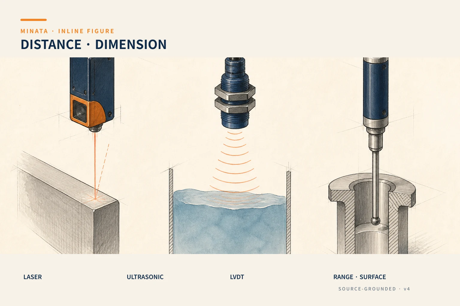
The right problem statement: measuring distance, position or dimension?
A sensor that "sees mm" may be used for entirely different goals:
- Distance/height: from the sensor head to the workpiece surface, for example checking a workpiece that is abnormally tall.
- Displacement/position: the travel of a slide, the deflection of a mechanism, runout or sag.
- Dimension: thickness, diameter, width or step difference. Many dimension measurements need two probes, a reference fixture, or a converting mechanism; a single sensor does not yet produce an absolute dimension.
- Level detection: a liquid/bulk material reaching a height, sometimes needing only a threshold rather than a continuous value.
This definition decides the mounting and calibration. For example, to measure sheet thickness: a laser looking at the top face gives the distance to the sensor, so the thickness result is only correct if the mechanical reference/bottom face is controlled. If the sheet face changes height on the conveyor, you may need two opposing probes or another reference. If the goal is a present/absent check, a threshold sensor may fit better than a complex analog measuring system.
Six parameters to lock before reading a catalog
1. Range and working point
Record the min–max distance of the real surface relative to the sensor mounting position, including fixture tolerance, vibration, recipe changes and mounting deviation. For a laser, the reference distance and measuring range belong to the specific model; for an LVDT, the stroke and the probe's preload/mechanical zone must match the travel. Do not just write "measure 0–100 mm" if the sensor will be mounted 300 mm from the part, or if the part can leave the measuring zone when the size changes.
2. Accuracy, linearity, resolution and repeatability
These are four different words. Resolution is about the small change step the system can represent; repeatability is about how consistently the result repeats under similar conditions; linearity/accuracy relates to the deviation from the true value over the range. The quality requirement must state the tolerance of the characteristic to be checked, then allocate the error budget to the sensor, fixture, reference, vibration, temperature and algorithm. Do not choose just because one catalog column shows a small µm number.
KEYENCE guides displacement-sensor selection by the desired accuracy, the target material/characteristics, the shape, the environmental conditions and the installation cost. This guidance matches design reality: a good sensor still does not allow reliable measurement if the reference face, fixture and vibration isolation are not defined.
3. Surface, material and viewing angle
Color, gloss, translucency, roughness, curvature and surface angle can change an optical result. A soft/film part may deform when a probe touches it; a porous object may absorb sound; a tilted surface may make the reflected signal not return to the ultrasonic or laser head the way the model expects. Take the worst-case sample, not the nicest reference plate, for testing.
4. Speed and measurement cycle
Fast-moving parts, a station with a short dwell time, or a vibrating object need a sample rate/response time capable of catching the event. High speed also wears a contact probe, which can bounce or fail to follow the surface. Read the "response time" together with the filter, output update and how the controller samples; if the PLC scans slower than the event, a fast sensor cannot save the data.
5. Environment and mounting space
Dust, oil, water, mist, heat, vibration, external light, airflow and dragged cables affect the three types differently. A laser lens surface must be kept clean; ultrasonic is affected by the sound-transmission conditions and has a blind zone; an LVDT/probe must avoid mechanical obstruction and needs the oil/water rating of the exact model checked. Also consider the mounting path and the maintenance path: can you remove the probe, adjust zero and clean it without dismantling the whole station?
6. Output, controller and the data-capture moment
An analog sensor may output different voltage/current depending on the model; an LVDT sometimes needs a dedicated conditioner/controller before it becomes a usable signal. State clearly the analog input, the signal range, the input resolution, the common/shield, the sample rate, the scale, the filter and the measurement trigger condition. A per-product dimension measurement needs to know when to read the value: by encoder, sensor trigger or a time window; reading any scan in the cycle easily captures a transition zone by mistake.
Laser sensor: prefer non-contact measurement and small spots
A laser displacement sensor uses different optical principles by series, for example triangulation, time-of-flight or confocal. So the word "laser" on a purchase request is not enough: you must choose the correct principle and model for the range, surface, target, speed and accuracy needed. KEYENCE states clearly that laser triangulation infers distance from the reflection angle, while confocal/ToF systems use a different principle; do not apply the specs of one type to another.
Laser is usually the first choice when:
- The part is soft, a film, a finished surface, or a hot object that should not be touched by a probe.
- You need to capture a small spot, inspect an edge, a step, a height, warp or a position on a part with clear geometry.
- You need a high sample rate per the model specification.
- You can arrange the optical path, block stray light and clean the lens during maintenance.
Beware of glossy, transparent and tilted surfaces
A laser beam does not "see everything alike." A glossy surface may reflect in another direction; changing color/reflectivity changes the received intensity; glass/film gives reflections from several faces; a curved or tilted surface changes the reflection point and spot. Some models/algorithms are designed to handle these targets better, but you must test with real samples and read the model's technical limits.
On site, also check the bracket's vibration. A sensor measuring a very small height, but on a bracket shared with a strongly vibrating motor/valve, will measure its own vibration too. Place the sensor on a rigid structure, check the cable strain relief, and use a reference artifact during acceptance. Use a filter only after knowing the vibration spectrum and the required response time.
Choosing the reference and the calibration method
A laser returns the distance to the sensor, so an absolute dimension needs a traceable mechanical datum/zero point. Record how the zero is set, the standard used for checking, the confirmation frequency and who is responsible. If the machine changes products, the recipe must preserve the setpoint/range/threshold with the corresponding fixture; do not let the operator adjust by eye on the HMI without limits.
Analog ultrasonic: use it when light is not reliable data
An ultrasonic sensor emits a sound wave and computes distance from the reflected signal. Because it does not rely on color or translucency like optics, it suits some targets that give lasers/photoelectric trouble: liquids, transparent objects, color-changing targets, or surfaces where level is measured by the sound-reflection principle. The analog version gives a continuous value, useful for measuring level/position within the range the sensor supports.
Choose analog ultrasonic when:
- The target and surface condition have been tested for stable sound reflection.
- The model's range/repeatability/response time meets the requirement, not just "has an analog output."
- You can leave a blind zone in front of the sensor and no other object passes through the measuring beam.
- Strong airflow, hot/cold air streams, foam, mist or sound-absorbing material have been assessed under process conditions.
The blind zone is part of the mechanical layout
The zone right at the sensor face may not allow reliable measurement. If the lowest/highest surface enters that zone, the system will lose data or change state unpredictably. Draw the cone/detection zone and every object that can pass through it, including tank walls, stiffening ribs, the gripper, flexible tubing and the operator during setup.
Measuring liquid and bulk material needs surface consideration
A liquid surface can wave, foam or change when the pump runs. Grains/powder can form a cone, absorb sound or move within the tank. Placing the sensor and the filter must be based on how the process operates: do you need instantaneous level, average level or just a full/empty threshold? Do not assume one analog value is the standard liquid level when the surface is fluctuating.
Air temperature and airflow
The speed of sound depends on the environmental conditions, so temperature/airflow can affect the measurement per the model's design/compensation. If the sensor is mounted near a furnace, a strong fan or a hot air stream, check the compensation documentation and test at the operating temperature. Do not take an air-conditioned-room calibration result as the sole evidence.
LVDT/contact sensor: trade contact force for a hard measuring point
An LVDT is a linear variable differential transformer, a method that measures displacement through electromagnetic change in a mechanism; in industrial products it usually appears as a contact sensor/probe with a tip touching the part. KEYENCE states that LVDT/contact distance sensors suit tight spaces, can place several heads close together, and measure positions hard to reach optically, such as an inner diameter. That is a real advantage when the part is hard, the fixture holds it stably, and the measurement needs to touch a defined point.
Choose LVDT/probe when:
- The surface is allowed to be touched and the probe force does not falsify the result or leave a mark.
- The geometry/space prevents a laser from seeing the measuring point, or several probes must sit close together.
- You need to measure a bore, runout, height, deflection or stroke with a suitable tip/fixture.
- You can keep the spindle/tip mechanism clean and accept a plan to check wear/repeatability.
Measuring force and contact direction can change the part
A soft object, a thin sheet, a film, rubber, a coated surface or a poorly fixtured part can be pushed off by the probe. Then the reading reflects the total deformation of the part and fixture, not just the dimension. Choose the tip, preload, mounting orientation and support point per the measurement drawing; test with a master and a borderline-tolerance part before putting the pass/fail criterion into the PLC.
Mechanical life must be managed
A contact sensor has a sliding surface and a tip; the measurement frequency, dust/chips, oil, side load and impact when the part enters all affect durability. Some series have a very high life spec under specified conditions, but you cannot transfer that number to another layout. Design a guard/guide for the part, avoid contact on a sharp edge, and have a zero/repeatability check routine in maintenance.
Conditioner and output
An LVDT head may need a compatible controller/conditioner to excite the coil, demodulate and output data. When the requirement states "LVDT analog," the BOM must separate the head, cable, controller, input module and license/communication if any. Check the signal range, resolution, response, the alarm on a cable/head break, and how the whole chain is calibrated.
Choosing by four typical situations
Checking a bottle-cap height or a step on a hard part
Laser can suit when non-contact measurement, a high line speed and a tested surface/gloss are needed. LVDT can also be good at a dwelling station with a rigid fixture, where the touching tip is placed at the exact point and optical-reflection effects must be avoided. Choose by real samples, speed and error budget, not by the price of the sensor head.
Measuring water/adhesive level in a tank with transparent walls
Analog ultrasonic is a candidate worth trying because it does not rely on translucency/color. Check the blind zone, foam, wave surface, temperature/airflow and how the sensor is placed on the tank lid. If the adhesive creates vapor or coats the sensor face, you must consider cleanability, protection and a different principle if the conditions exceed the datasheet.
Checking the thickness of a film or a soft sheet
Avoid a contact probe if the measuring force deforms the object. A laser or a suitable non-contact method may need two probes/a reference fixture to separate thickness from conveyor-position fluctuation. What matters is designing a complete measuring system, not just choosing an accurate sensor.
Measuring an inner diameter/hidden point
An LVDT/contact probe has the advantage when a small head reaches into a position where a laser beam has no line of sight. Design the fixture and tip so the probe travels along the measuring direction and avoids side load; use a master to set zero and check repeatability at the start of the shift.
Integrating analog into the PLC: the measurement does not end at the sensor head
For all three types, the path into the PLC/HMI must be specified clearly:
- Choose the correct analog input (voltage/current or a dedicated controller) per the datasheet.
- Wire the leads, shield, ground/common per the manual of the sensor and module, avoiding parallel routing with power cables when not recommended.
- Scale the raw value per the range/signal of the exact sensor part, using a consistent unit in the code/HMI.
- Define when to sample: trigger, encoder, machine cycle or the moment the part is still.
- Filter/average per the process requirement, while keeping the ability to detect a fault needing a fast response.
- Check zero/span/repeatability with a suitable standard, recording the acceptance result and the alarm threshold.
Do not put a pass/fail threshold into the program before confirming the whole chain of fixture, target, sensor, I/O, scale and read moment. An uncommon but very costly error is a correct scale on the HMI while the PLC logic uses a raw count or a different unit; naming the variables/functions with their unit avoids this error.
Common mistakes
- Using a single laser to conclude thickness while the reference face changes. Design a suitable datum or two probes.
- Choosing by resolution without considering repeatability, accuracy and the fixture. Write the error budget against the real pass/fail criterion.
- Mounting ultrasonic to measure close to the sensor face. Leave a blind zone and test every surface position.
- Using a probe on a soft object/film. The contact force can change the very object being measured.
- Setting a filter to mask vibration/a weak bracket. Fix the mechanics and check the layout first.
- Wiring analog correctly but scaling the wrong range. Check the range/output per the model, the I/O configuration and the reference measurement.
- Ignoring lens, tip and master-calibration maintenance. This is the operational-design part of the measuring system.
Quick selection checklist
- [ ] Do you need to measure distance, position, thickness or a dimension with a clear datum/fixture?
- [ ] Do the range, reference distance/stroke and fixture tolerance cover the real range?
- [ ] Does the requirement distinguish accuracy, linearity, resolution and repeatability?
- [ ] Is the target surface glossy, transparent, tilted, soft, porous or changing by recipe?
- [ ] Does the speed/sampling/trigger capture the exact measurement moment in the cycle?
- [ ] Does the laser have a clean optical path; ultrasonic a blind zone; the LVDT a suitable force/tip/orientation?
- [ ] Are the sensor, controller/conditioner, analog I/O and scale a compatible chain?
- [ ] Have you tested the worst-case sample, real vibration/heat/environment and master calibration before locking the threshold?
If you are building a station to measure dimension, level or position, MINATA can help define the reference, sensor principle, I/O and acceptance method with you before locking the BOM. See MINATA's Engineering & Manufacturing service.
References
More in the Device Selection series
View all MINATA technical articles