Manufacturing Engineering #02: CNC Milling, Turning or Wire EDM — Choosing by Shape and Tolerance
Manufacturing Engineering #02: CNC Milling, Turning or Wire EDM — Choosing by Shape and Achievable Tolerance
Short answer: choose turning when the part is a body of revolution about one axis, choose CNC milling for a prismatic shape with several faces, pockets and holes in various directions, and only choose wire EDM when you need a sharp-cornered profile, a thin wall, or a hardened material a cutter cannot reach. The three methods do not fully replace each other: each follows one geometry and one tolerance band, and a complex part usually passes through two or three operations. This article helps you look at a drawing and predict which way to order the machining, and which tolerance is reasonable so you avoid a "sky-high" quote or returned parts.
Quick comparison of the three methods
| Criterion | Turning | CNC milling | Wire EDM |
|---|
| Suitable geometry | Rotational: shafts, bushings, threads, cones | Prismatic: plates, pockets, steps, holes in many directions | Vertical 2D/2.5D profile, sharp inner corners |
| Typical dimensional tolerance | IT7–IT8 (±0.01–0.03 mm) | IT7–IT9 (±0.01–0.05 mm) | IT6–IT7 (±0.005–0.015 mm) |
| Usual surface roughness Ra | 0.8–3.2 µm | 0.8–3.2 µm | 0.4–1.6 µm |
| Hardened material (>45 HRC) | Hard, needs special tools | Hard, tools wear fast | Cuts well, independent of hardness |
| Inner corner (fillet R) | By the tool nose | At least the milling-cutter radius | Very small, the wire radius (~0.1 mm) |
| Material removal rate | Fast | Medium | Slow |
| Relative cost per part | Low | Medium | High |
| Material requirement | Any metal | Any metal | Only conductive material |
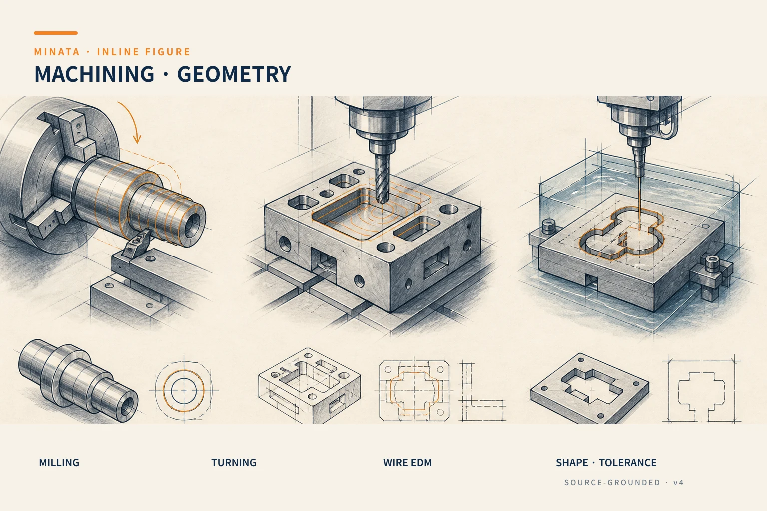
Turning: when the part revolves about one axis
Turning is a method in which the workpiece rotates while the tool stays and translates to cut. So every turnable surface is a surface of revolution about the axis of rotation: outer cylinder, inner bore, cone, groove, thread and end face. If you hold a drawing and see a part symmetric about a center line — a motor shaft, a bushing, a threaded connector, a pulley, a locating pin — it almost certainly should be turned first.
Turning's biggest advantages are speed and concentricity. Because the workpiece rotates about a fixed center, the outer diameter, inner bore and end face machined in the same setup are very concentric with each other, usually achieving runout under 0.01 mm. This is something milling struggles to do with a long shaft. A modern CNC lathe with live tooling can even mill a keyway, drill a cross hole and tap right on the lathe, reducing the number of setups.
Turning's typical tolerance is IT7–IT8, corresponding to about ±0.01–0.03 mm for a part a few tens of millimeters in size. Tighter than that (IT6 and below) requires grinding after turning. For roughness, finish turning gives Ra 0.8–1.6 µm normally; a finer finish needs diamond turning or grinding.
Turning's limit: it cannot make off-center flats, square pockets or asymmetric profiles. When a part has both a cylindrical part and a prismatic part (for example a shaft with a square flange head), it must pass through both turning and milling.
CNC milling: when the shape has many faces in many directions
Milling is the opposite: the tool rotates while the workpiece is clamped on the table and moves along the X-Y-Z axes (plus A, B if it is a 4–5-axis machine). This lets milling handle almost any prismatic shape: a base plate with many holes, an enclosed pocket, a stepped face, a groove, a 3D curved mold profile.
3-axis milling handles well the parts where every surface to cut is visible from above. When a part has surfaces in many directions, it needs re-clamping several times — each re-clamp is a source of error. This is where 4–5-axis milling has value: it tilts or rotates the workpiece so one clamping machines many faces, keeping the positional relationship between faces (which the drawing often constrains with positional and parallelism tolerances).
A point to remember when designing for milling: every inner corner of a pocket must have a fillet radius, and that radius must not be smaller than the milling-cutter radius. No milling cutter can make a perfectly sharp square inner corner. If the drawing states an inner corner of R0 (sharp square), the milling shop must ask back or move that part to wire EDM. The deeper the pocket, the longer and thinner the tool must be, the easier it vibrates and leaves marks, so keep the depth-to-diameter ratio under about 4–5 for a stable result.
Typical milling tolerance is IT7–IT9. With a good fixture and machine, finish milling reaches ±0.01–0.02 mm at small dimensions; large dimensions or several setups open it up to ±0.05 mm or more.
Wire EDM: when the cutter cannot reach, or the material is hardened
Wire EDM (Wire Electrical Discharge Machining) does not cut with mechanical force. It uses an electric spark between a thin copper/brass wire (diameter 0.1–0.25 mm) and the workpiece, gradually eroding the material in a deionized-water medium. Because there is no cutting force and it does not depend on material hardness, EDM does three things milling and turning struggle with:
- Cutting hardened material. Die steels SKD11, SKH51 after hardening to 58–62 HRC are almost unmillable; wire EDM cuts them normally. This is why stamping dies, punches and dies are almost always wire-cut after heat treatment.
- Very sharp inner corners. The minimum inner-corner radius is only the wire radius plus the spark gap, about 0.1 mm — much smaller than a milling cutter.
- Thin walls and slender profiles that a mechanical cutting force would deform or break.
In return, wire EDM is slow and expensive, only creates a "vertically swept" profile along the wire direction (2D, or 2.5D with a U-V tilt axis), cannot make a free 3D curved surface like milling, and the material must be conductive. Wire EDM tolerance is very good, usually IT6–IT7, reaching ±0.005 mm with a precise machine and several cuts (rough cut then re-cut the contour finely).
Choosing: read the drawing to decide
The drawing-reading process to decide:
- A part revolving about one axis? → Turning is the base. With a keyway or cross hole, turn on a machine with live tooling or move to milling in a later step.
- A prismatic part with many faces, pockets, many holes in various directions? → CNC milling. If the positional constraint between faces is tight or faces are in many directions, consider 4–5-axis milling to reduce setups.
- A sharp inner corner R < 0.5 mm, a very thin wall, or a profile on hardened material? → Wire EDM.
- A tolerance tighter than IT6, a surface needing Ra < 0.4 µm? → None of the above is enough; you must add grinding or fine EDM after rough machining.
In practice, a typical mold part passes through all three: rough milling to shape → heat treatment → grinding the reference faces → wire-cutting the precise profiles after hardening. So when ordering machining, do not think "choose one machine" but think by the process sequence: what is done before hardening, what is left for after hardening.
Tolerance and cost go together
The most expensive mistake when writing a drawing is stating a tolerance tighter than the function really needs. Each tighter tolerance grade is a cost grade: a ±0.1 mm dimension is milled in one pass; forcing it to ±0.01 mm may require an added grinding operation, more inspection, more scrap. The general experience: state a tight tolerance only on the exact functional mating dimensions (a bearing-mounting hole, a locating pin, a sealing contact face), and leave the rest as a coarse general tolerance per a standard such as JIS B 0405 medium class.
This series also has a dedicated article going deep into how IT7–IT9 tolerances drive the machining cost — see Manufacturing Engineering #05 — How the tolerance you write decides the machining cost.
Example: reading a real part
Suppose the drawing is a guide plate for a stamping die: 120 × 80 × 20 mm, material SKD11, with four holes for guide bushings toleranced H7, two U-shaped profile grooves 6 mm wide with an inner corner R0.2 mm, and a hardness requirement of 60 HRC after heat treatment.
How to read it to plan the process sequence:
- The block and the four holes: 3-axis CNC milling in the soft (unhardened) state to shape the envelope, drill the four holes leaving an allowance. At this point you do not machine to the fine dimension because hardening will distort it.
- Heat treatment: harden to 60 HRC. After this the material is too hard for finish milling.
- Grinding the two reference faces: restore flatness and parallelism after hardening, creating a reference for later operations.
- Wire EDM: finish-cut the four H7 holes and the two U grooves — because the grooves have an inner corner R0.2 mm (even the smallest milling cutter struggles, and it is on 60 HRC material), and the H7 holes need a stable IT7 tolerance on hardened material.
If you skip the principle "leave the precise profile for after hardening" and try to finish-mill everything while soft, the plate will bow and lose dimension after hardening, and must be scrapped. This is a classic example of a part belonging not to "one machine" but to a milling → harden → grind → wire-cut chain.
Common mistakes
- Stating a square inner corner R0 for a milled part. A round milling cutter cannot make a sharp square corner; either fillet it or move to wire EDM (much more expensive).
- Ordering wire EDM for a part milling can make. Wire EDM is slow and expensive; use it only when you truly need a sharp corner, a thin wall or hardened material.
- Requesting turning for a non-axisymmetric part. A prismatic part, off-center flats cannot be turned; they must be milled.
- Forgetting the heat-treatment order. The precise profile should be wire-cut after hardening; if you finish-mill first then harden, the part distorts and loses dimension.
- Stating a uniformly tight tolerance. It raises the price without adding functional value.
Quick selection checklist
- [ ] Is the part symmetric about one axis? Yes → prefer turning.
- [ ] Does it have many faces, pockets, holes in many directions? Yes → CNC milling (4–5-axis if the positional constraint is tight).
- [ ] Are there sharp inner corners, thin walls, or hardened material > 45 HRC? Yes → wire EDM.
- [ ] A tolerance tighter than IT6 or Ra < 0.4 µm? Yes → you need grinding / fine EDM in addition.
- [ ] Have you clearly separated the functional dimensions (stated tight) from the free dimensions (left as a general tolerance)?
- [ ] Have you determined the process sequence around the heat-treatment point?
If you have a drawing and are unsure which way to order machining, or want to optimize tolerances to reduce cost while still meeting function, MINATA can review the drawing and advise a suitable machining approach before quoting. See MINATA's Engineering & Manufacturing service.
Reference: the Ra roughness ranges by machining method (各種加工法による粗さの範囲 table) and IT tolerance grades per JIS B 0401, cross-checked with the MISUMI catalog technical tables. See in detail how tolerance drives cost in Manufacturing Engineering #05.
More in the Manufacturing Engineering series
View all MINATA technical articles